JeepOfTheseus
Well-Known Member
- Thread starter
- #1
As I alluded to in other threads, I got a set of the FOX Sway Bar Disconnects (abbreviated as QSE) and just wrapped up the install. Over the course of a couple weeks, I did the physical install followed by running the wiring and then wrapping it up with some trekking in uncharted territory. For those unfamiliar with the system, they are effectively APEX autoLYNX with an electro-pneumatic powered disconnect (in my own words).
Initial impressions: they are beefy. There are wheel backspacing considerations that need to be made, and they even include knuckle bump stop spacers (which I installed and then removed because it appears I have enough clearance without, and I will warn: if you have to install them - you will notice the increased turning radius).

Physical installation is easy, they bolt right up. Wiring is a different story. To be clear: the harness they provide is top-notch, but they provide their own momentary push-button which they suggest drilling into the cup holder for placement. The system also includes an electronic controller, which (per their instructions) get tucked behind the passenger footwell. This did not work for me, so I placed it in the engine bay. Instructions didn't say you can't do this, so I'm hoping for the best.

Regarding my setup specifically: I already have an 8 switch rocker panel on my dash from VOSwitch. Ahead of all this, I actually relocated my winch switch to the engine bay to free up one of the switches. Unfortunately, it wasn't until I got the QSE kit that I realized they use a momentary action. Luckily, VOSwitch was able to send me a momentary rocker...but it gets worse. The LED on the provided QSE button stays on to indicate the links are disconnected, even though the button has been released. The momentary rocker is only lower independent - meaning the lower LED has a dedicated positive terminal, but the upper is jumped internally from the switched NO terminal (i.e. it only comes on while the rocker is pressed).
It gets worse. The QSE switch in/out only carries ~5V (likely because it's going through a circuit board). So now I needed to figure out not only how to provide switched 5V power, but also make the upper LED function separate of the mechanical switch position. The solution? Two relays.
First, I swapped the wires for Terminal 2 and 3 on the rocker switch. 2 is normally 12V in, 3 is normally 12V out (i.e. the ACC). Since the upper LED gets power from 3 (hence why it lights up when you press the switch), now 3 is always hot and the LED gets constant power while the ACC still gets the switched power it needs from Terminal 2. However, to prevent it from always being on: I grounded Terminal 8 (the upper LED negative) through an NO relay. 30 & 87 complete the ground to chassis, while 86 (coil trigger) is wired to the QSE 12V LED lead. That means the upper LED is now grounded whenever QSE would have previously been supplying 12V power to the provided button. FWIW, I used a flyback diode between the QSE 12V pin out and my relay, because I didn't want the relay coil to send anything back into the (presumably) sensitive electronics.
Second, I used a relay for the QSE switch in/out. Similarly, 30 & 87 complete the QSE switch circuit, while 86 is wired to my rocker switch (Terminal 2, the switched NO contact). Now the system gets the momentary action it needs, while retaining whatever voltage/resistance magic is going on.

Some how, some way...I got it right on the first try. Rocker switch disconnects/reconnects the links, and the upper LED reflects the state of the system.
Initial impressions: they are beefy. There are wheel backspacing considerations that need to be made, and they even include knuckle bump stop spacers (which I installed and then removed because it appears I have enough clearance without, and I will warn: if you have to install them - you will notice the increased turning radius).
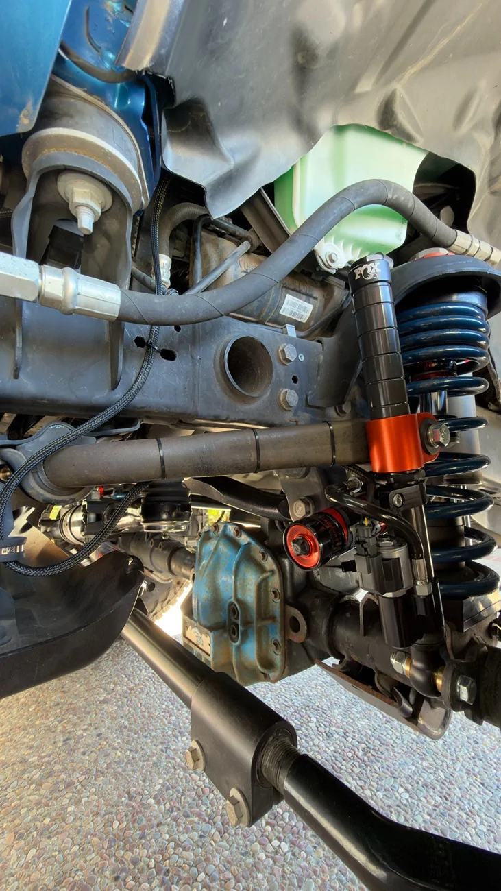
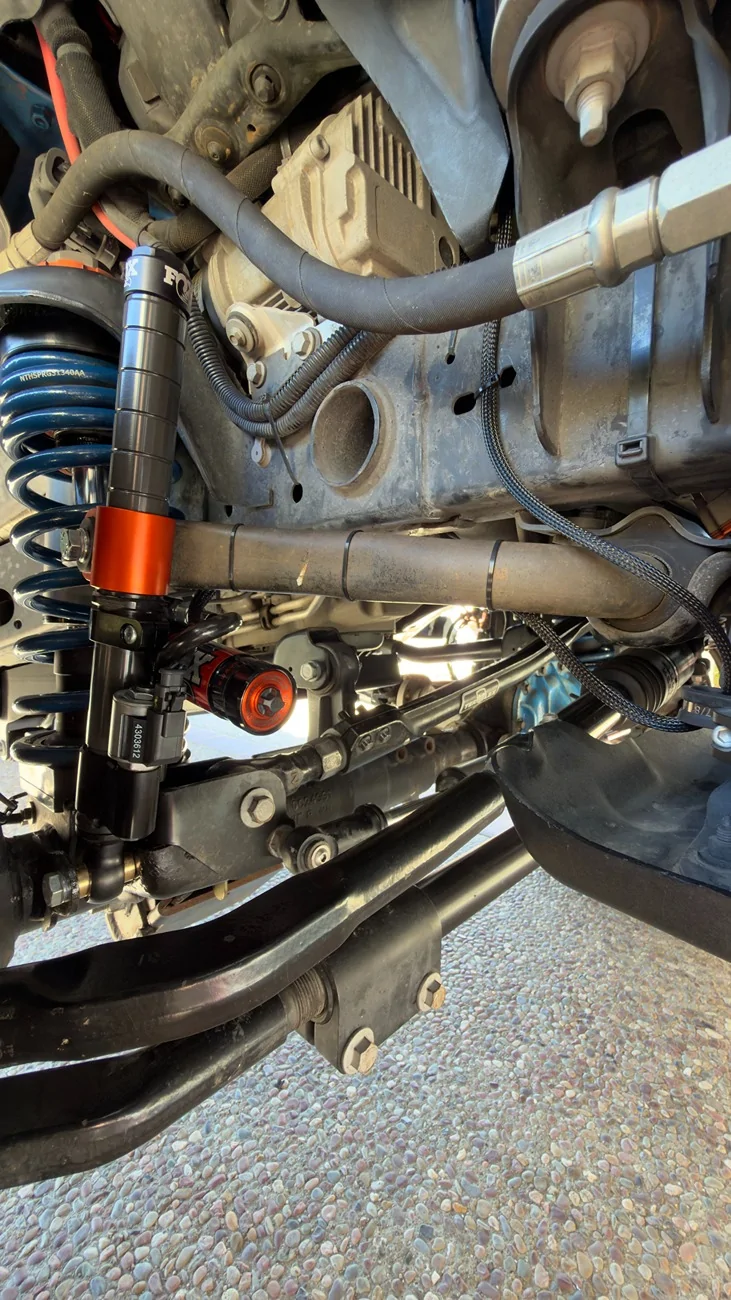
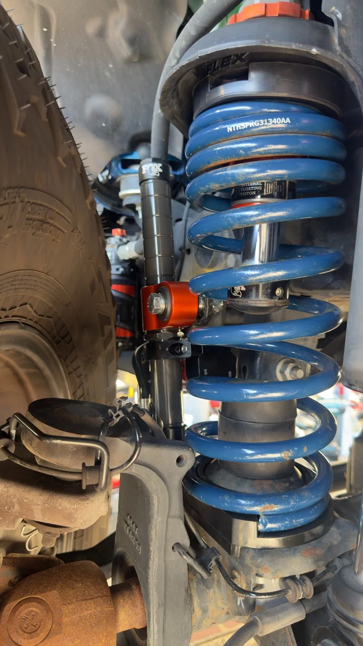
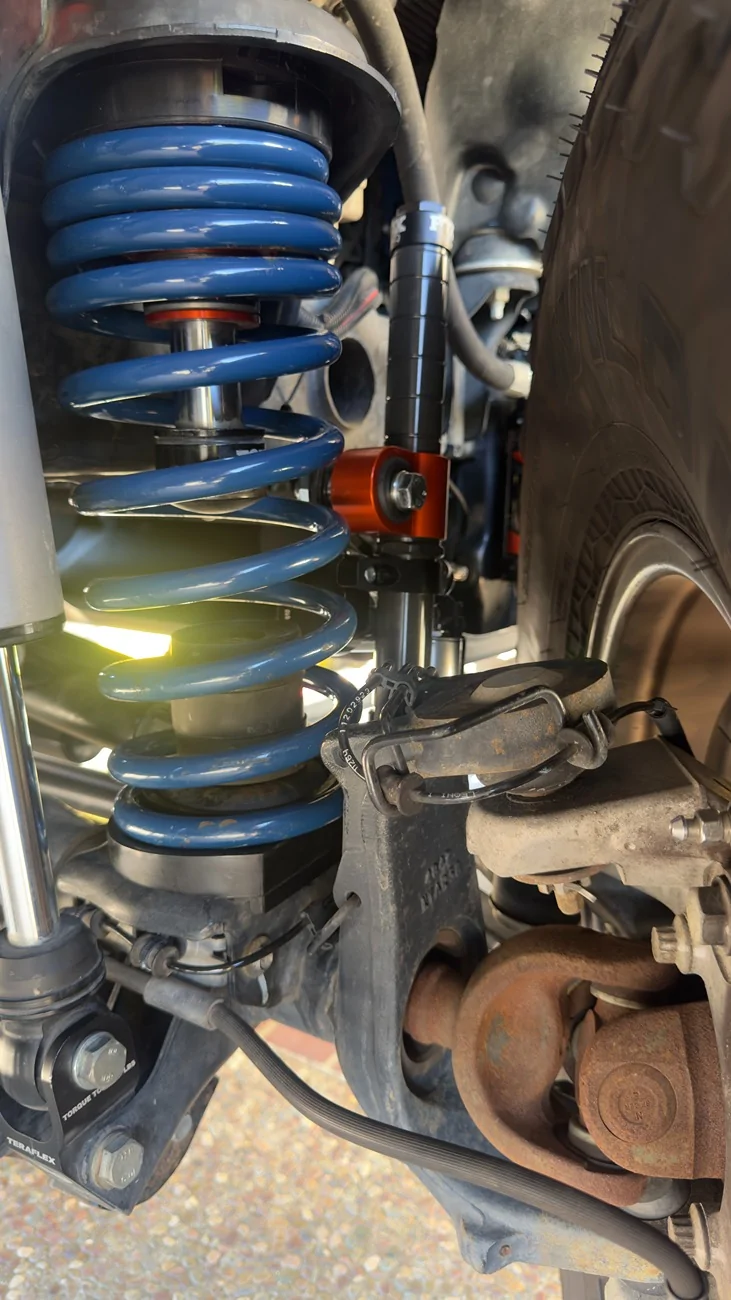
Physical installation is easy, they bolt right up. Wiring is a different story. To be clear: the harness they provide is top-notch, but they provide their own momentary push-button which they suggest drilling into the cup holder for placement. The system also includes an electronic controller, which (per their instructions) get tucked behind the passenger footwell. This did not work for me, so I placed it in the engine bay. Instructions didn't say you can't do this, so I'm hoping for the best.
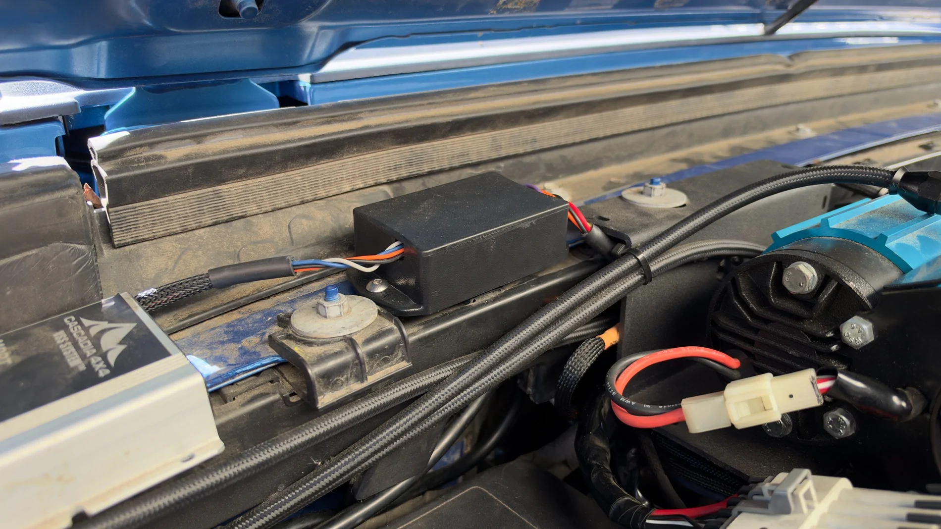
Regarding my setup specifically: I already have an 8 switch rocker panel on my dash from VOSwitch. Ahead of all this, I actually relocated my winch switch to the engine bay to free up one of the switches. Unfortunately, it wasn't until I got the QSE kit that I realized they use a momentary action. Luckily, VOSwitch was able to send me a momentary rocker...but it gets worse. The LED on the provided QSE button stays on to indicate the links are disconnected, even though the button has been released. The momentary rocker is only lower independent - meaning the lower LED has a dedicated positive terminal, but the upper is jumped internally from the switched NO terminal (i.e. it only comes on while the rocker is pressed).
It gets worse. The QSE switch in/out only carries ~5V (likely because it's going through a circuit board). So now I needed to figure out not only how to provide switched 5V power, but also make the upper LED function separate of the mechanical switch position. The solution? Two relays.
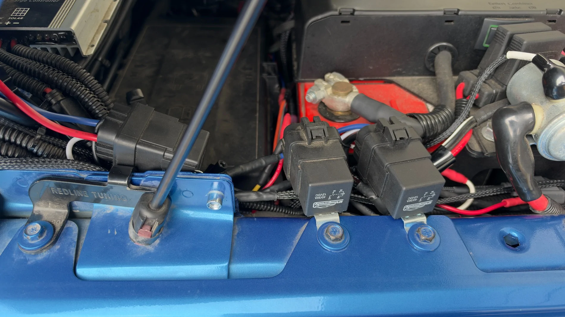
First, I swapped the wires for Terminal 2 and 3 on the rocker switch. 2 is normally 12V in, 3 is normally 12V out (i.e. the ACC). Since the upper LED gets power from 3 (hence why it lights up when you press the switch), now 3 is always hot and the LED gets constant power while the ACC still gets the switched power it needs from Terminal 2. However, to prevent it from always being on: I grounded Terminal 8 (the upper LED negative) through an NO relay. 30 & 87 complete the ground to chassis, while 86 (coil trigger) is wired to the QSE 12V LED lead. That means the upper LED is now grounded whenever QSE would have previously been supplying 12V power to the provided button. FWIW, I used a flyback diode between the QSE 12V pin out and my relay, because I didn't want the relay coil to send anything back into the (presumably) sensitive electronics.
Second, I used a relay for the QSE switch in/out. Similarly, 30 & 87 complete the QSE switch circuit, while 86 is wired to my rocker switch (Terminal 2, the switched NO contact). Now the system gets the momentary action it needs, while retaining whatever voltage/resistance magic is going on.
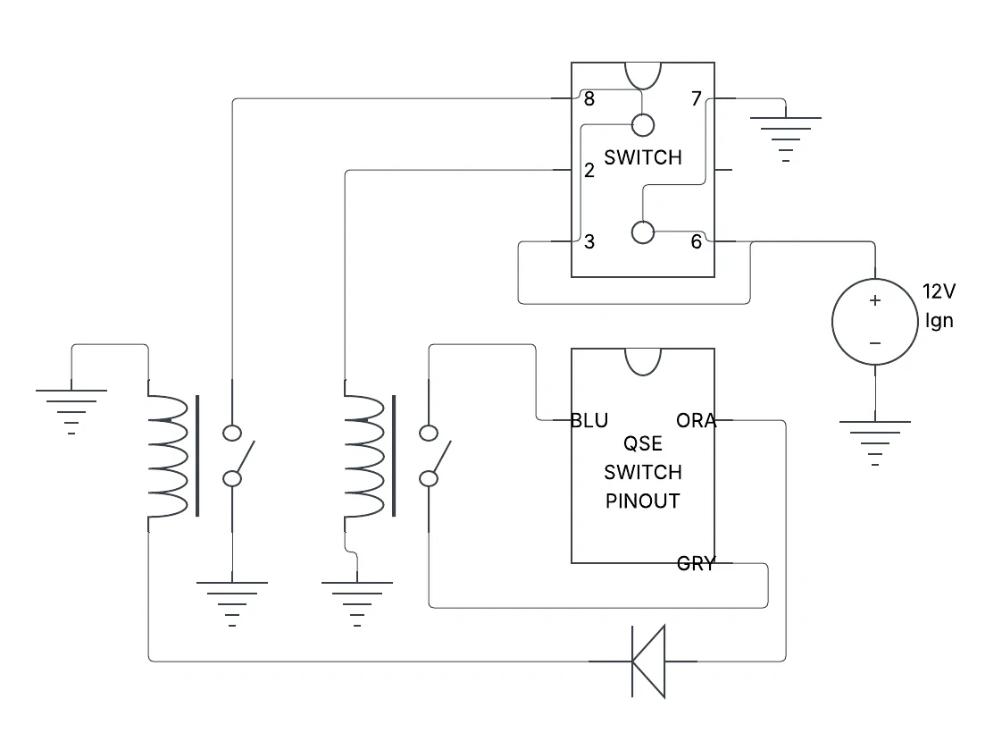
Some how, some way...I got it right on the first try. Rocker switch disconnects/reconnects the links, and the upper LED reflects the state of the system.
Sponsored
Last edited: