Pisgahlj
Member
- First Name
- Matt
- Joined
- Feb 3, 2019
- Threads
- 2
- Messages
- 22
- Reaction score
- 15
- Location
- Western NC
- Vehicle(s)
- 23 Gladiator
- Thread starter
- #1
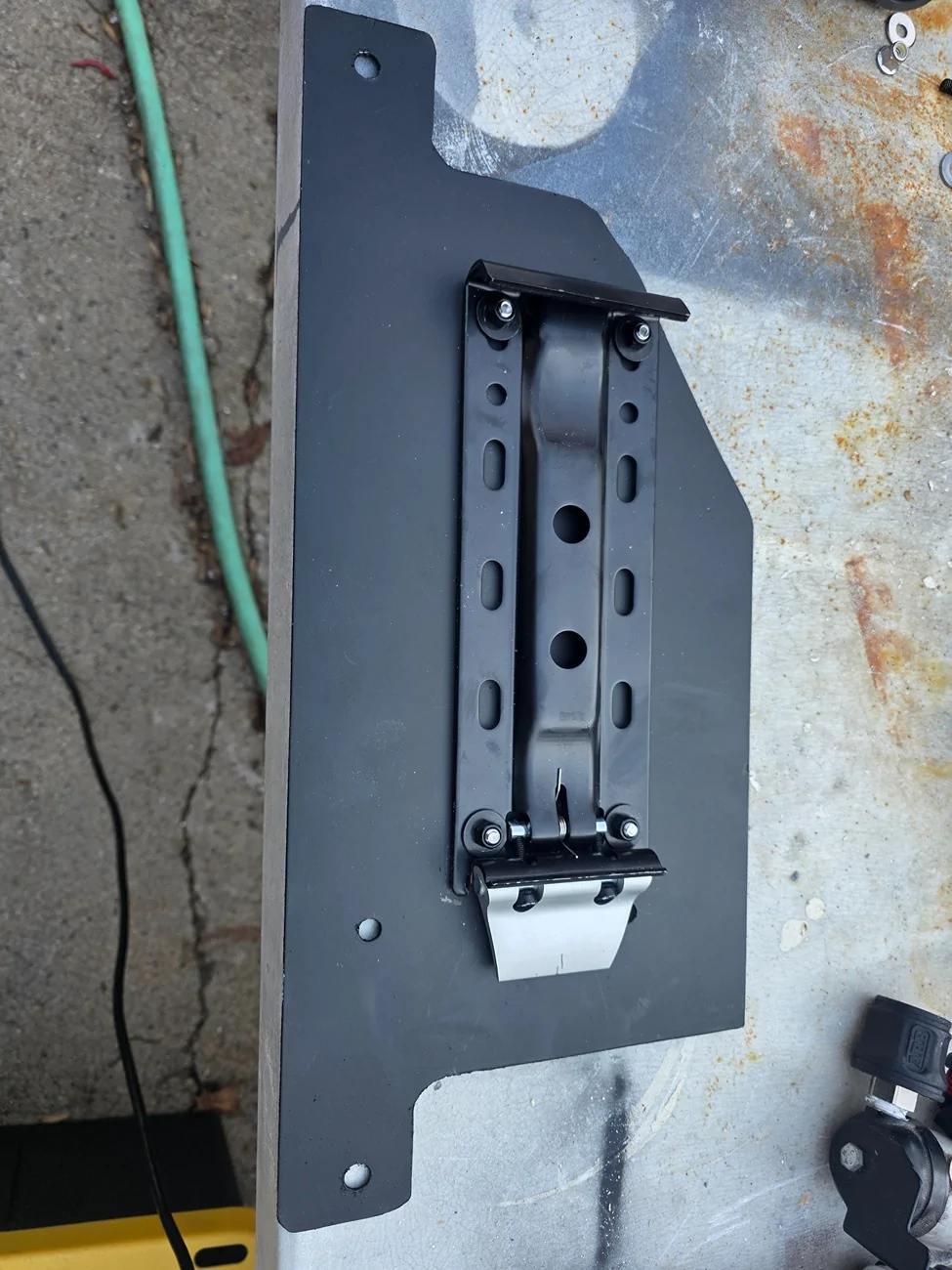
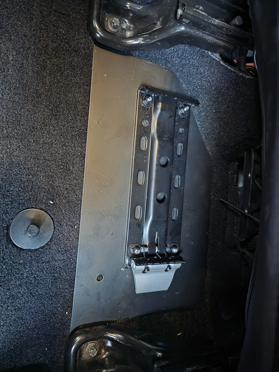
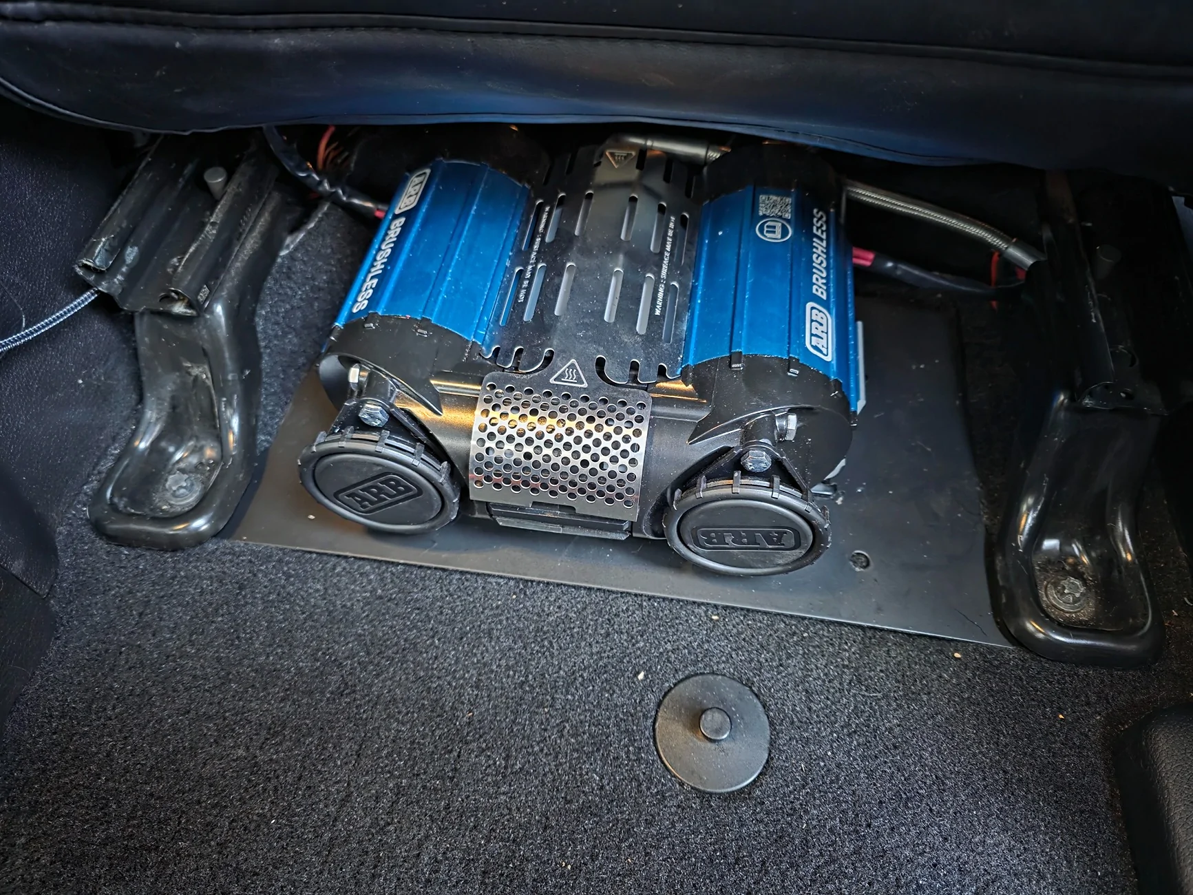
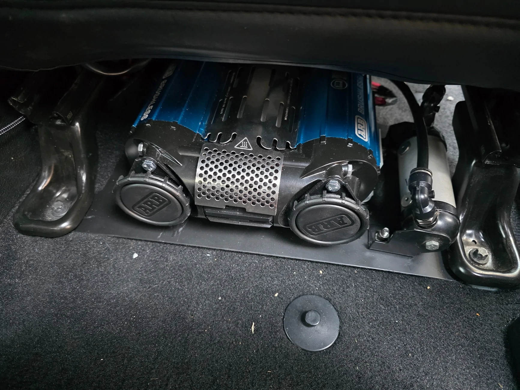
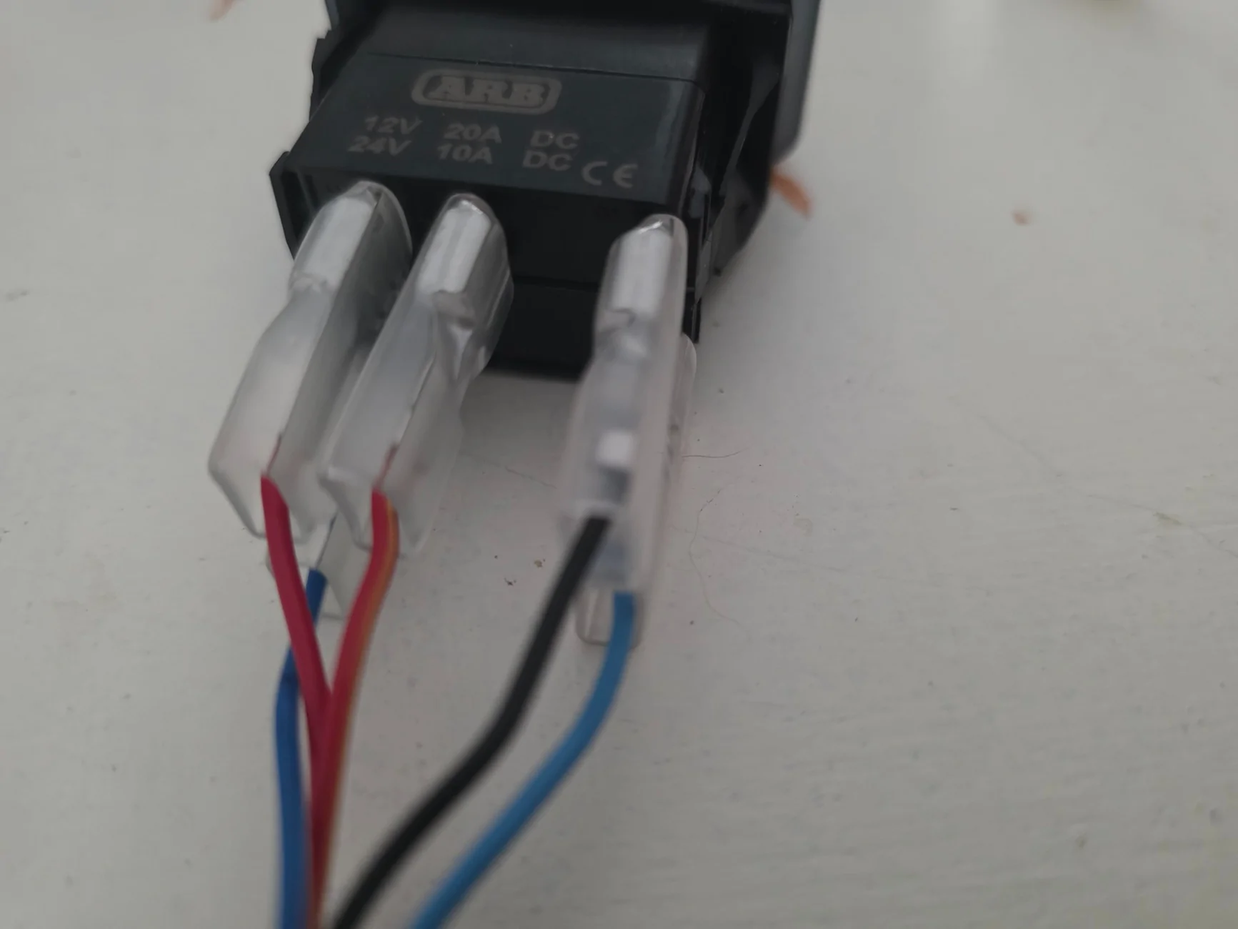
In the middle of adding my standard ARB Twin into my new 23 Gladiator, I had the opportunity to buy an almost new Brushless Twin at a good discount. The biggest issue with the Brushless Twin is the harness is almost all one piece and a mess. The new ARB Brushless Twin Wiring harness is needlessly complex if you are only looking at using it for a compressor and not for lockers. Even using it for lockers, the harness limits where the solenoids are located. As my new Gladiator came with Aux Switches, I'm not going to be using the stock ARB switch either and will use the Aux switches to control the compressor.
After watching several install videos, I was able to figure out what to take apart. There was only 1 wire that needed to be cut to remove the switches from the Harness. This can easily be reconnected in the future with a butt splice.
Steps are below.
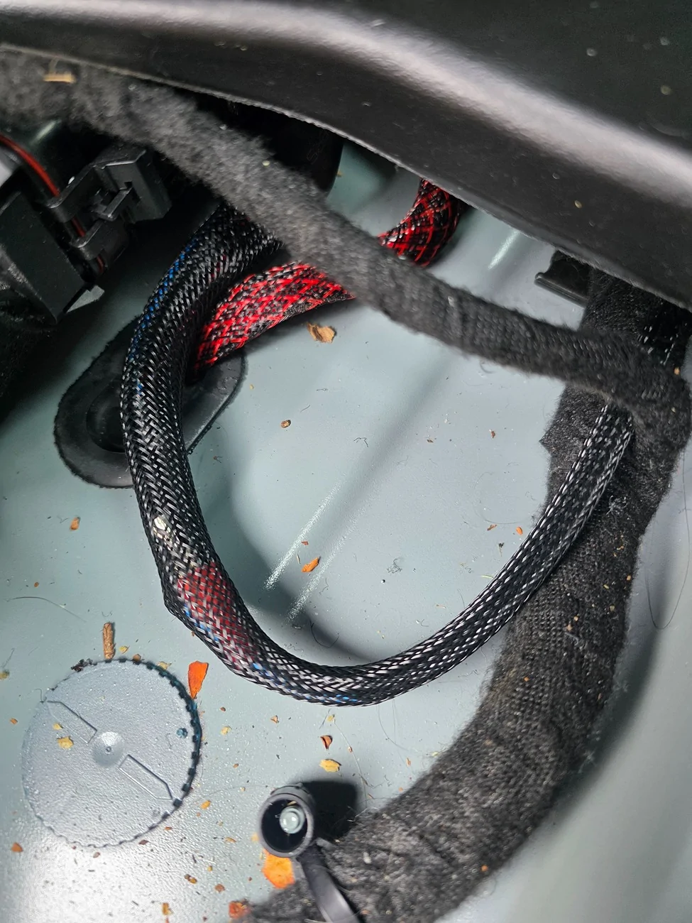
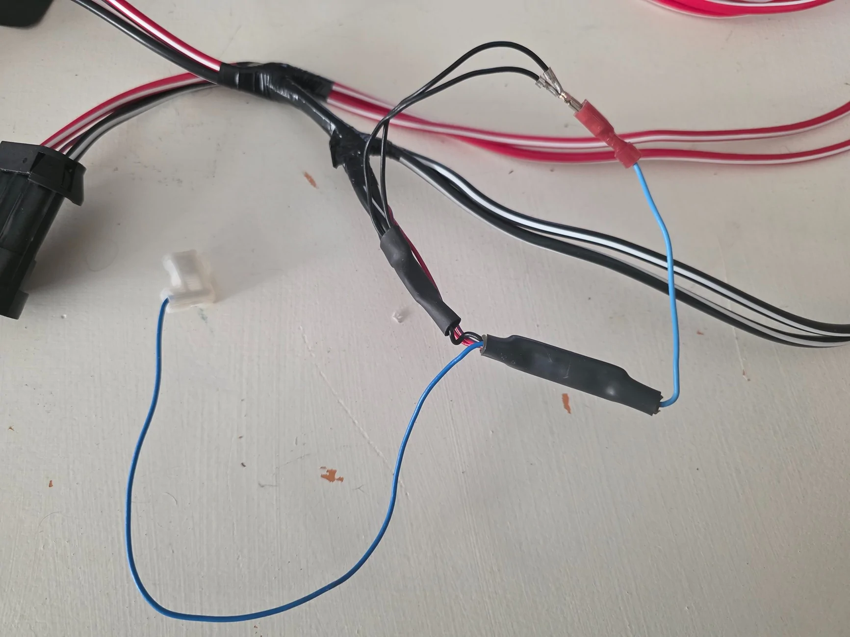
1. Layout the harness and locate the circuit board layered within the harness near the compressor connections. Remove the wrap from the circuit board and switch wires until the switch wires are separated from the circuit board. Do not remove the wrap/heat shrink around the circuit board. I unwrapped the harness all the way to the first x wrap as shown.

2. Unwrap the solenoid connection wires to remove the Red Wire from the blue wire. I used a sharp pocket knife with the blade turned away from myself and the wires.
3. Unpin the Black wires from the locker solenoid connections. Insert a pick into the connection and depress the tab while gently pulling on the wire.
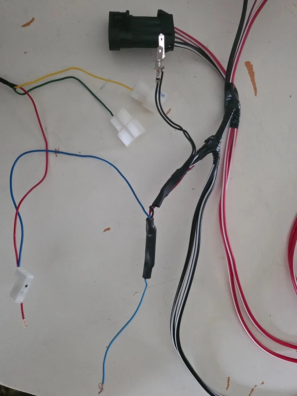
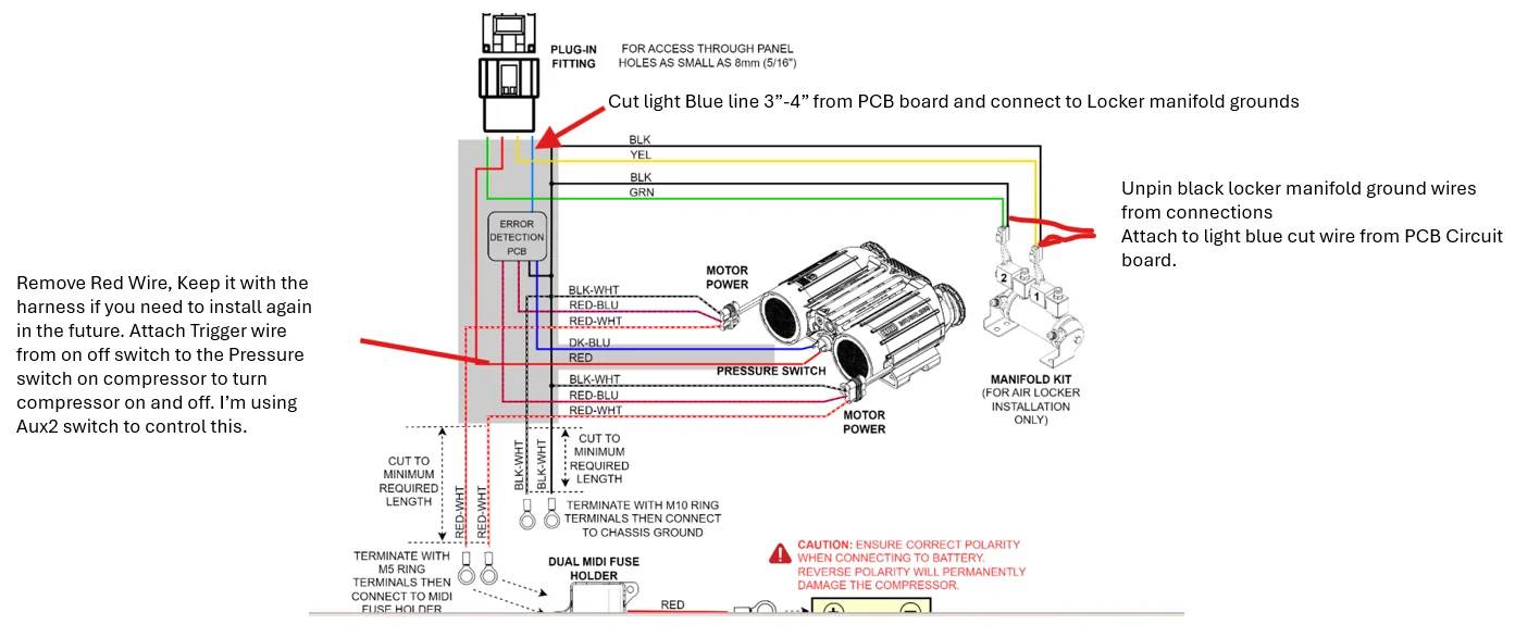
4. Cut the blue wire coming out of the circuit board about 3 - 4 inches from the end of the circuit board. It is essentially a ground and has conductance to the 2 black ground wires that are ahead of the circuit board.
5. Crimp a female spade connection on this blue wire and connect to one of the 2 black ground wires. I actually opened up the female end a little more and connected both then taped it all together.

The Harness switches are now separated removing 10 feet of wiring harness that runs from the compressor to the first disconnect at the switch harness.
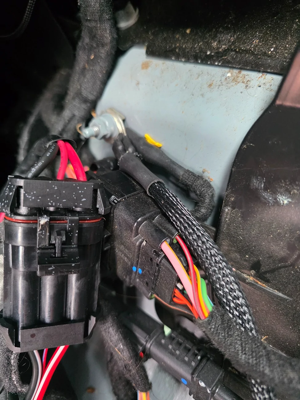
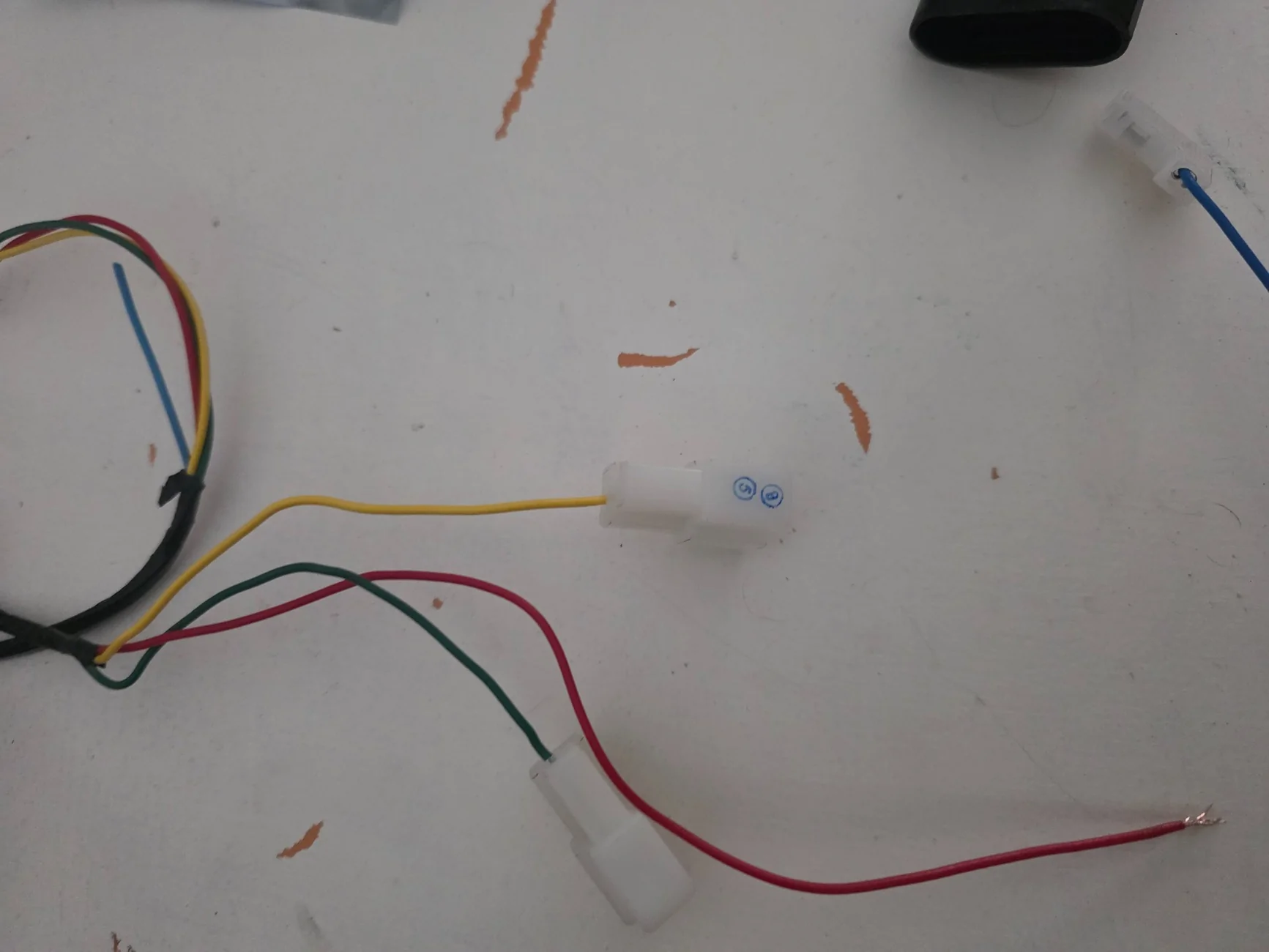
I when to Ace Hardware and picked up 5 feet of 18GA stranded wire and attached the stock 90* female spade (from the red wire shown above,) to one end and a butt splice to the other. This butt splice is connected to my Aux2 Switch. It's one of the 15 Amp switches.
To get the compressor working, just connect the Blue wire to one of the pressure switch terminals, and the new red wire to the other. It doesn't mattery which one, there is no polarity here on this switch. Connect the power wires to the battery and the ground wires to the chassis and you are back in business.
If using the factory switch, The new red wire will be connected to the outside terminalof the 3 terminals, Ground on the other end with power wire to the center terminal. Light Blue wire next to the Black is actually the wire running out of the circuit board, i.e. a ground, The Blue with white stripe(next to the red) is the lighting connection for the switch.

After watching several install videos, I was able to figure out what to take apart. There was only 1 wire that needed to be cut to remove the switches from the Harness. This can easily be reconnected in the future with a butt splice.
Steps are below.
1. Layout the harness and locate the circuit board layered within the harness near the compressor connections. Remove the wrap from the circuit board and switch wires until the switch wires are separated from the circuit board. Do not remove the wrap/heat shrink around the circuit board. I unwrapped the harness all the way to the first x wrap as shown.
2. Unwrap the solenoid connection wires to remove the Red Wire from the blue wire. I used a sharp pocket knife with the blade turned away from myself and the wires.
3. Unpin the Black wires from the locker solenoid connections. Insert a pick into the connection and depress the tab while gently pulling on the wire.
4. Cut the blue wire coming out of the circuit board about 3 - 4 inches from the end of the circuit board. It is essentially a ground and has conductance to the 2 black ground wires that are ahead of the circuit board.
5. Crimp a female spade connection on this blue wire and connect to one of the 2 black ground wires. I actually opened up the female end a little more and connected both then taped it all together.
The Harness switches are now separated removing 10 feet of wiring harness that runs from the compressor to the first disconnect at the switch harness.
I when to Ace Hardware and picked up 5 feet of 18GA stranded wire and attached the stock 90* female spade (from the red wire shown above,) to one end and a butt splice to the other. This butt splice is connected to my Aux2 Switch. It's one of the 15 Amp switches.
To get the compressor working, just connect the Blue wire to one of the pressure switch terminals, and the new red wire to the other. It doesn't mattery which one, there is no polarity here on this switch. Connect the power wires to the battery and the ground wires to the chassis and you are back in business.
If using the factory switch, The new red wire will be connected to the outside terminalof the 3 terminals, Ground on the other end with power wire to the center terminal. Light Blue wire next to the Black is actually the wire running out of the circuit board, i.e. a ground, The Blue with white stripe(next to the red) is the lighting connection for the switch.
Sponsored
Last edited: