Sponsored

IDEAL ARB PLACEMENT

Pliny

Well-Known Member
First Name
Philip
Joined
Dec 17, 2022
Threads
21
Messages
228
Reaction score
376
Location
AZ
Vehicle(s)
22 JTR, 99 F250 SD, 24 BMW X3
Occupation
Retired
So black and purple are the only two wires I need? Something has to go to the switch. Or am I wrong if I'm using the aux switches?
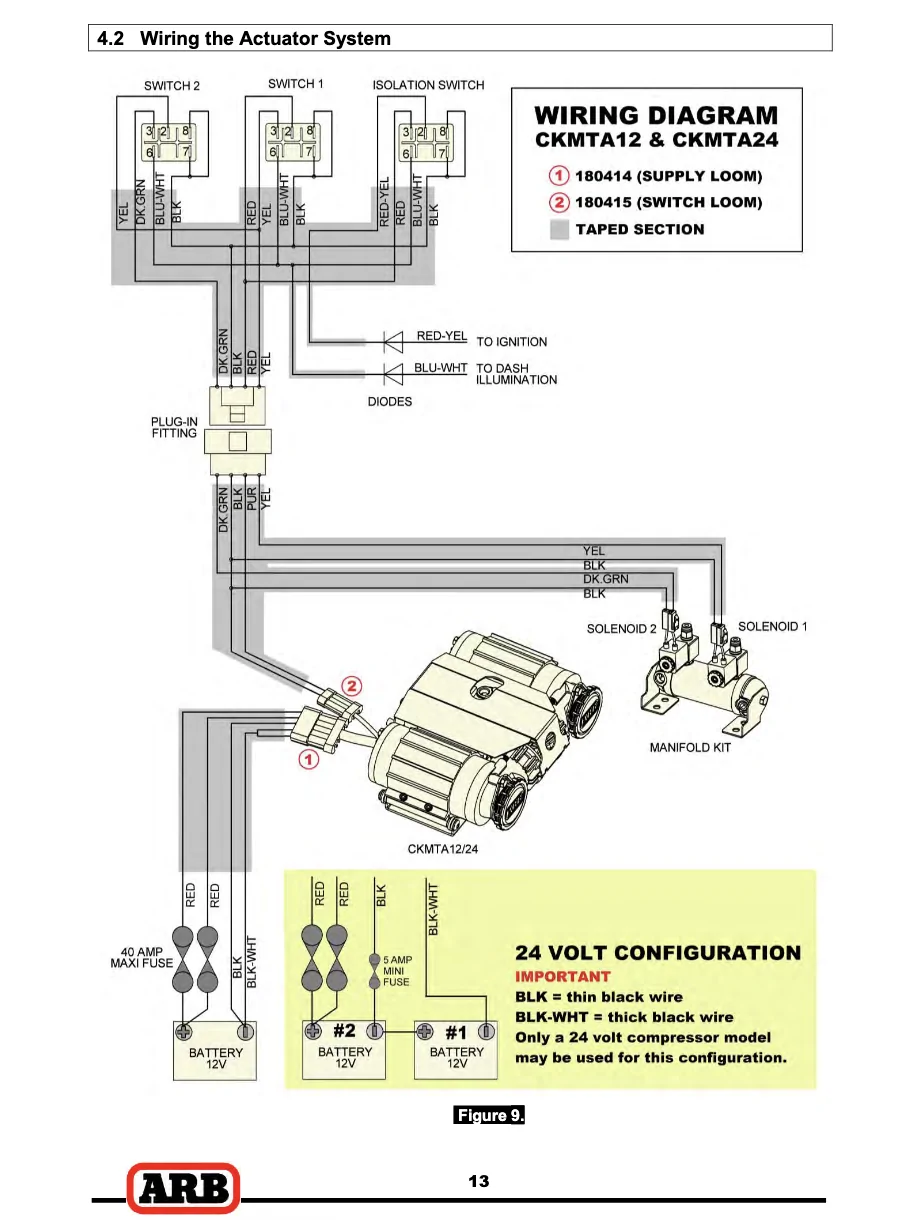
I wired the Aux 4 wire in the passenger footwell to the purple wire. I left the black wire that goes to connector 2 floating. In the ARB wiring harness for connector 2 that black wire serves as the ground for the LEDs in the ARB switches and the ground for the solenoids on the ARB manifold.

In the ARB wiring harness for connector 1, it has 5 pins. Two thick red wires, one to each motor, two thick black wires, again one to each motor, and the thin black wire that is the ground for the fan and relays in the dual compressor assembly (and likely is electrically connected to the black wire in connector 2, though I didn't test that myself). You can see in that diagram where they short the two motor grounds together in their harness leaving one thick black wire with a white stripe to connect to the chassis ground right by the battery.

There was a thread somewhere (not necessarily in this forum, can't recall where exactly) where a guy had done the install and had grounded the little black wire on connector 2 separately from the black and black-white wires in connector 1. Was using the compressor and bad things happened because his ground connection of the black / black-white wires came loose. All of the current from the motors was then tying to flow through the little black wire in connector 2 which is way too small to handle that many amps, without a bunch of smoke / melting / maybe fire. That is why I left the black wire in connector 2 floating.

If you're going to do your own two terminal switch, then one terminal of the switch should go to an ignition on wire (like the red-yellow wire in the diagram) and then the other terminal of the switch would get connected to the purple wire.
Sponsored


Free2roam

Well-Known Member
First Name
Robert
Joined
Mar 1, 2021
Threads
30
Messages
5,434
Reaction score
11,563
Location
89521
Vehicle(s)
Gladiator
Occupation
Fabricator by trade/ Maintenance Mechanic
If you're going to do your own two terminal switch, then one terminal of the switch should go to an ignition on wire (like the red-yellow wire in the diagram) and then the other terminal of the switch would get connected to the purple wire.

I was just either going to use the ARB switch that comes with it, or an aux switch. My question is what if any wires go to the ARB switch? This is the point of confusion. Do I need to go and have a wire ran from aux to switch or only purple to aux? Leave small black floating. Got that. Ground two large black wires. Got that.
 

Pliny

Well-Known Member
First Name
Philip
Joined
Dec 17, 2022
Threads
21
Messages
228
Reaction score
376
Location
AZ
Vehicle(s)
22 JTR, 99 F250 SD, 24 BMW X3
Occupation
Retired
I was just either going to use the ARB switch that comes with it, or an aux switch. My question is what if any wires go to the ARB switch? This is the point of confusion. Do I need to go and have a wire ran from aux to switch or only purple to aux? Leave small black floating. Got that. Ground two large black wires. Got that.
I am genuinely trying to be helpful. Referring back to this diagram:

Jeep Gladiator IDEAL ARB PLACEMENT Screenshot 2026-03-01 at 5.06.14 AM

If you are going to use the ARB supplied wiring that connects to connector 1 on the compressor assembly, you need to connect the four wires at the other end as shown. Two large red wires, one for compressor motor A, the other for compressor motor B, the large black-white wire that is the ground for both compressor motors A and B, and then the little black wire that serves as the gound for everything else (relays, fan, solenoids, LEDs).

The ARB supplied switches have 5 terminals on the back. They have 2 LEDs in each of them. One LED is intended to be on when you turn your dash lights on so that you can find the switch in the dark. The other is an indicator light which will light up when the switch is in the on position and the ignition is on (assuming you wire it up as shown). Each LED in the switch has its' own ground terminal on the back, the black gound wire goes to terminals numbered 7 & 8 in the diagram.

I don't know of an easily accessible wire in the cab that you would connect to the blue-white to get the symbol on the switch to be illuminated when the dash lights are on.

If you want to use the ARB compressor on/off switch with the ARB supplied harnesses, that switch gets plugged in to the connector with the red, red-yellow, blue-white and black wires as shown in the diagram.

If you want to use the ARB compressor on/off switch but cut up the ARB switch harnesses then:

1.) black wire from connector 2 needs to go to black wires going to terminals 7 & 8 on the isolation (on/off) switch in the diagram. This provides the ground to the LEDs in the switch.

2.) red-yellow wire in the harness connects to an ignition wire and goes to terminal 2 on the isolation (on/off) switch. This provides the power to the switch.

3.) purple wire from connector 2 needs to be connected to the red wire from terminal 6 of the isolation (on/off) switch. This is the output of the switch.

4.) connection of the blue-white wire to illuminate the switch when the dash lights are on is up to you to figure out.

If you want to use an Aux wire in the passenger footwell and cut up the ARB switch harness then:

1.) Aux wire gets connected to purple wire from connector 2.
 

Free2roam

Well-Known Member
First Name
Robert
Joined
Mar 1, 2021
Threads
30
Messages
5,434
Reaction score
11,563
Location
89521
Vehicle(s)
Gladiator
Occupation
Fabricator by trade/ Maintenance Mechanic
I am genuinely trying to be helpful. Referring back to this diagram:

Screenshot 2026-03-01 at 5.06.14 AM.webp

If you are going to use the ARB supplied wiring that connects to connector 1 on the compressor assembly, you need to connect the four wires at the other end as shown. Two large red wires, one for compressor motor A, the other for compressor motor B, the large black-white wire that is the ground for both compressor motors A and B, and then the little black wire that serves as the gound for everything else (relays, fan, solenoids, LEDs).

The ARB supplied switches have 5 terminals on the back. They have 2 LEDs in each of them. One LED is intended to be on when you turn your dash lights on so that you can find the switch in the dark. The other is an indicator light which will light up when the switch is in the on position and the ignition is on (assuming you wire it up as shown). Each LED in the switch has its' own ground terminal on the back, the black gound wire goes to terminals numbered 7 & 8 in the diagram.

I don't know of an easily accessible wire in the cab that you would connect to the blue-white to get the symbol on the switch to be illuminated when the dash lights are on.

If you want to use the ARB compressor on/off switch with the ARB supplied harnesses, that switch gets plugged in to the connector with the red, red-yellow, blue-white and black wires as shown in the diagram.

If you want to use the ARB compressor on/off switch but cut up the ARB switch harnesses then:

1.) black wire from connector 2 needs to go to black wires going to terminals 7 & 8 on the isolation (on/off) switch in the diagram. This provides the ground to the LEDs in the switch.

2.) red-yellow wire in the harness connects to an ignition wire and goes to terminal 2 on the isolation (on/off) switch. This provides the power to the switch.

3.) purple wire from connector 2 needs to be connected to the red wire from terminal 6 of the isolation (on/off) switch. This is the output of the switch.

4.) connection of the blue-white wire to illuminate the switch when the dash lights are on is up to you to figure out.

If you want to use an Aux wire in the passenger footwell and cut up the ARB switch harness then:

1.) Aux wire gets connected to purple wire from connector 2.
I appreciate the help in all honesty. I just am not all that electrically inclined. The explanation seems straight forward. All I really need is an on /off, whether it's from the ARB switch or the aux switches. I mean literally an on/off.
The black/ red wires I've already got ran to the engine bay. That's easy.
No chance of ever having lockers.
 

Free2roam

Well-Known Member
First Name
Robert
Joined
Mar 1, 2021
Threads
30
Messages
5,434
Reaction score
11,563
Location
89521
Vehicle(s)
Gladiator
Occupation
Fabricator by trade/ Maintenance Mechanic
So now what? I've got all the wires hooked up. Purple going to #1 aux switch. (Grey/pink) Hots to battery, ground to ground lug in engine bay. Both plugs plugged into the compressor. I've checked power at the main plug. 12v+ at plug. Compressor does not turn on. :angry::angry::angry::angry:
 

Sponsored

Pliny

Well-Known Member
First Name
Philip
Joined
Dec 17, 2022
Threads
21
Messages
228
Reaction score
376
Location
AZ
Vehicle(s)
22 JTR, 99 F250 SD, 24 BMW X3
Occupation
Retired
So now what? I've got all the wires hooked up. Purple going to #1 aux switch. (Grey/pink) Hots to battery, ground to ground lug in engine bay. Both plugs plugged into the compressor. I've checked power at the main plug. 12v+ at plug. Compressor does not turn on. :angry::angry::angry::angry:
If you took the big fuses going to the compressor motors out during the install, did you put them back in their fuse holders?

Check the Aux 1 fuse.

Go to the menu for the Aux buttons in the center display and make sure that the setting for Aux 1 is set to be persistent (not momentary) and I think there may be a setting to be always on or on with iginition. You'll want it to be on with the ignition.

Is the ignition on? Is the engine running?

If that all checks out, then pull the big fuses for the compressor motors, turn the ignition on, then turn Aux 1 on. You should hear the relays on the compressor click and the fan on the compressor should be running. If not, then that narrows it down to the wiring from the Aux 1 wire to the compressor.
 

Free2roam

Well-Known Member
First Name
Robert
Joined
Mar 1, 2021
Threads
30
Messages
5,434
Reaction score
11,563
Location
89521
Vehicle(s)
Gladiator
Occupation
Fabricator by trade/ Maintenance Mechanic
If you took the big fuses going to the compressor motors out during the install, did you put them back in their fuse holders?

Check the Aux 1 fuse.

Go to the menu for the Aux buttons in the center display and make sure that the setting for Aux 1 is set to be persistent (not momentary) and I think there may be a setting to be always on or on with iginition. You'll want it to be on with the ignition.

Is the ignition on? Is the engine running?
I imagine I'm not supposed to have any voltage going through aux 1 if the button is not pressed. Because for some reason I do.

If that all checks out, then pull the big fuses for the compressor motors, turn the ignition on, then turn Aux 1 on. You should hear the relays on the compressor click and the fan on the compressor should be running. If not, then that narrows it down to the wiring from the Aux 1 wire to the compressor.
I've got 13.8 volts to purple wire aux 1 pressed engine running. Fused pulled on power wires. No solenoids clicked on compressor.
Also fuse F93/92 both good.
As well as aux 1 to ignition on latching setting.
I'm guessing I'm not supposed to have any voltage going through aux 1 when it is not engaged. But for some reason I do.
Sponsored

 
Last edited:


Top