Sponsored

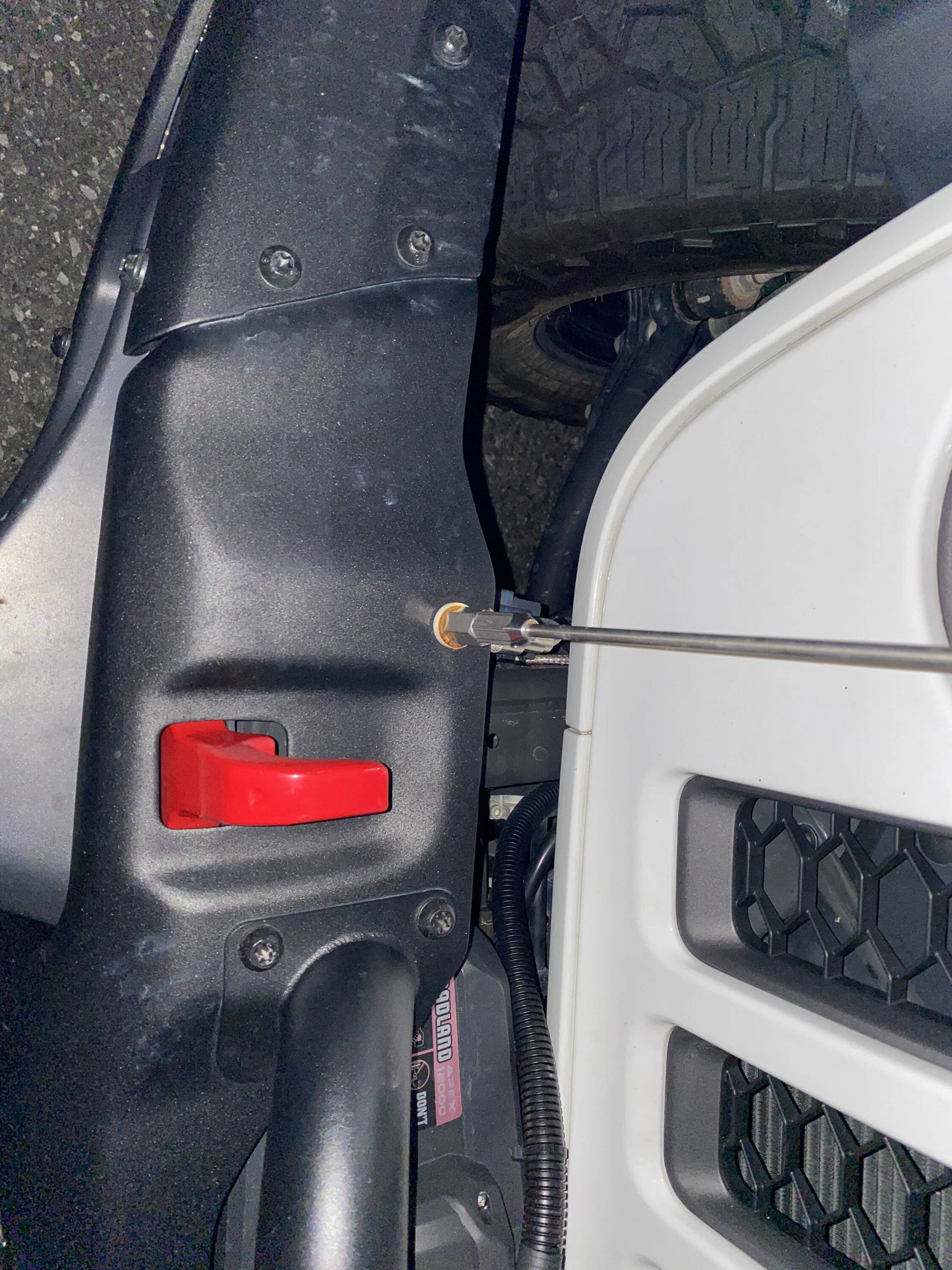
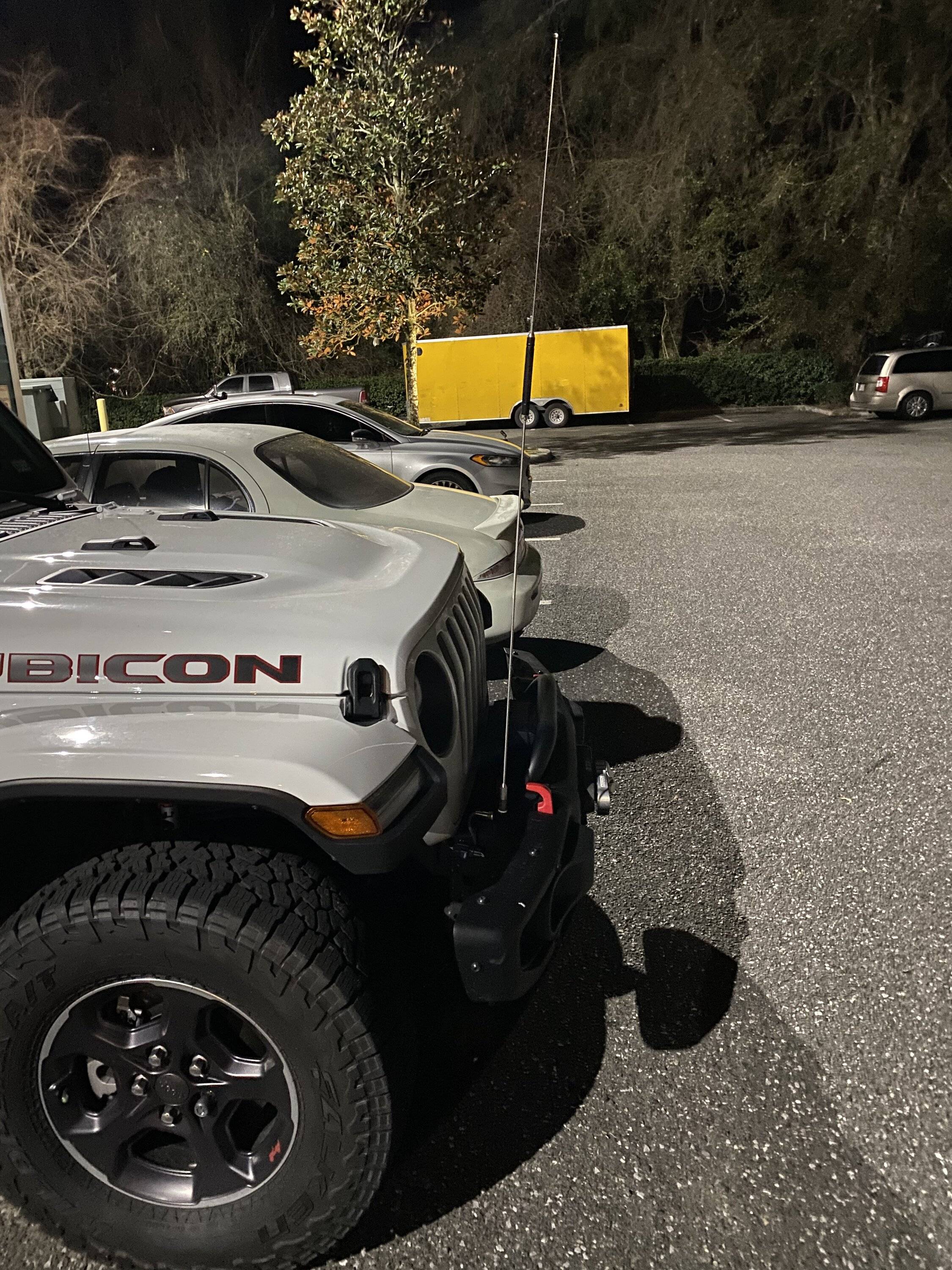
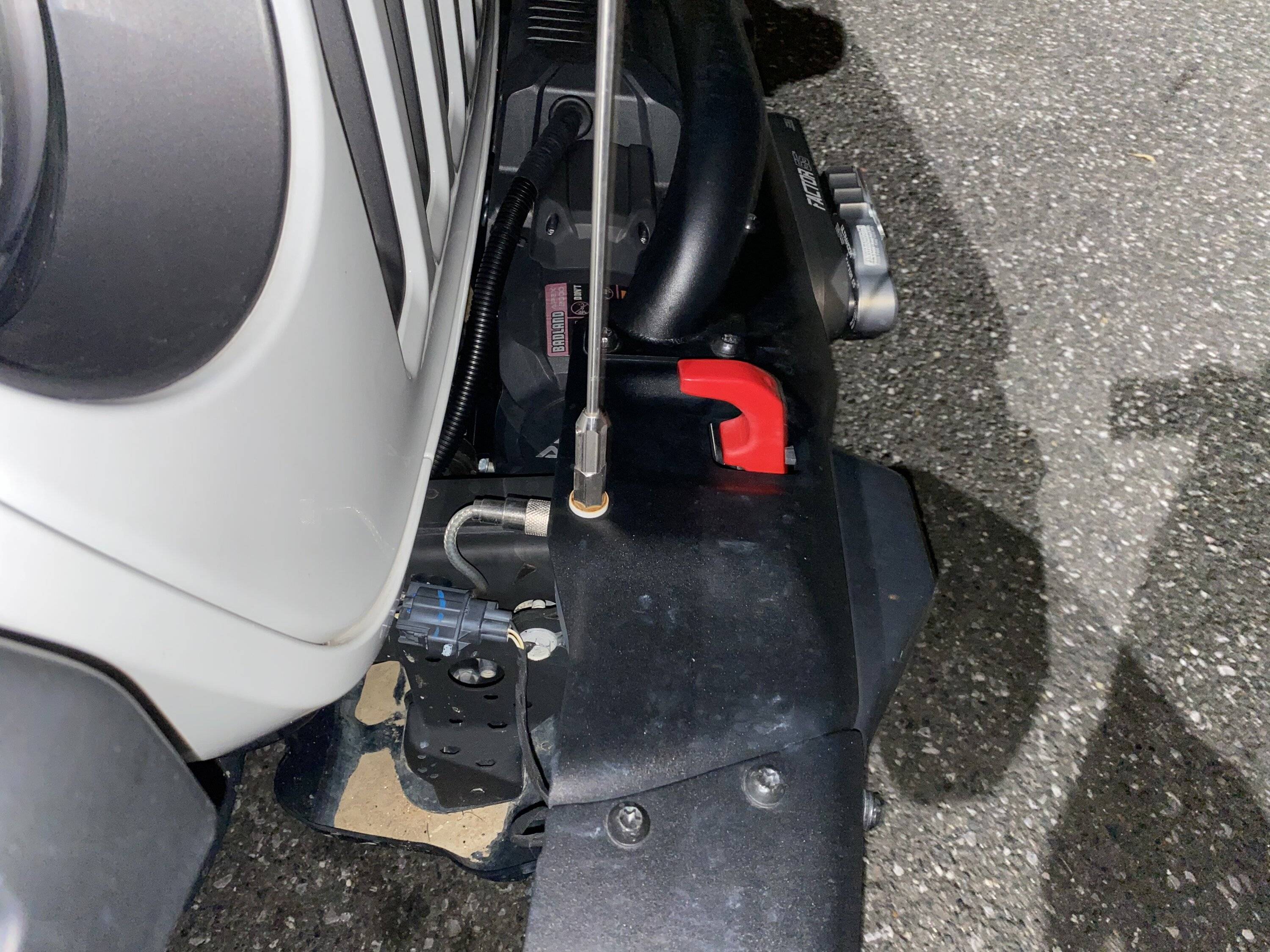
GMRS / CB antenna locations - near A pillar or mid point on hood

OP
OP
chorky

chorky

Well-Known Member
First Name
Chad
Joined
Feb 26, 2022
Threads
175
Messages
3,466
Reaction score
3,802
Location
Montana
Website
www.youtube.com
Vehicle(s)
'22JTR, '06 LJ, '06 TJ GE
Build Thread
Link
Occupation
GIS Specialist
No problem, even running both cables wrapped tightly together the full length of the truck. All coax is inherently shielded, just some is better than others. There will be way more signal pickup between antennas compared to cable leakage.
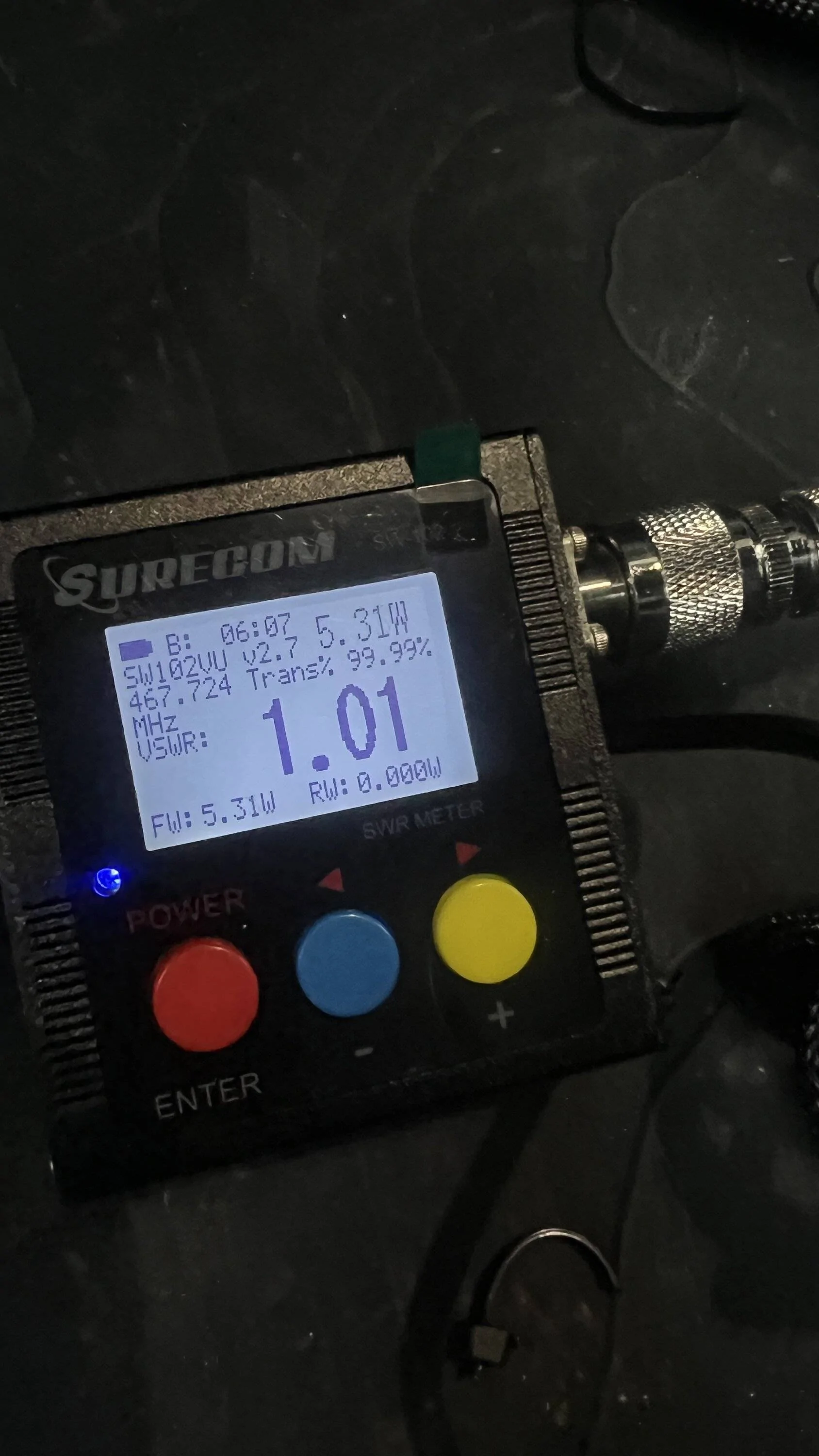
Just threw things together quickly to check power/swr - of course the fancy new midland mic doesn't work so I there on the old one.

How much do you trust these numbers? SWR seems perfect. Although the antenna being from Midland should be pre-tuned I would imagine....

CH 1
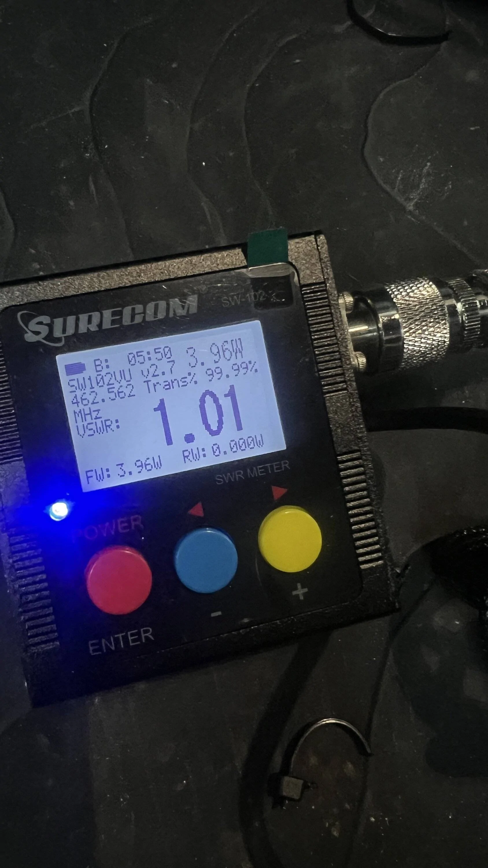
Jeep Gladiator GMRS / CB antenna locations - near A pillar or mid point on hood IMG_9937


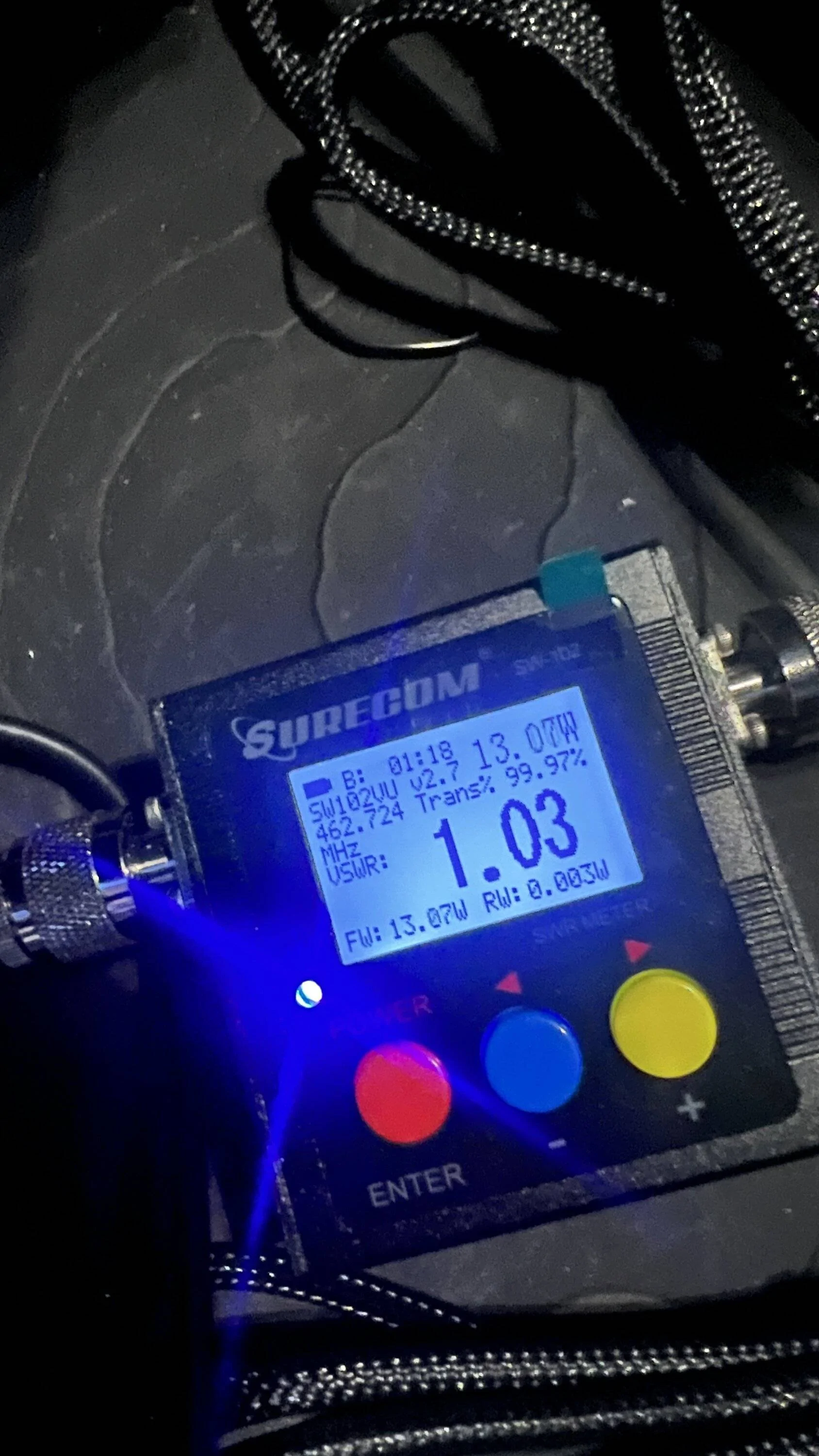
CH 22
Jeep Gladiator GMRS / CB antenna locations - near A pillar or mid point on hood IMG_9938


The extra coax is just bound together and zipped like it came in the package (not in a circle). I do not have a dummy load yet - so this is straight to the antenna. Not quite sure what to think of the listed wattage. I know some thread you or somebody mentioned about power being absorbed along the way so a 15w radio typically wont actually put out 15 watts, but only 5 on a repeater channel on high? that seems awful low....
Sponsored
 
OP
OP
chorky

chorky

Well-Known Member
First Name
Chad
Joined
Feb 26, 2022
Threads
175
Messages
3,466
Reaction score
3,802
Location
Montana
Website
www.youtube.com
Vehicle(s)
'22JTR, '06 LJ, '06 TJ GE
Build Thread
Link
Occupation
GIS Specialist
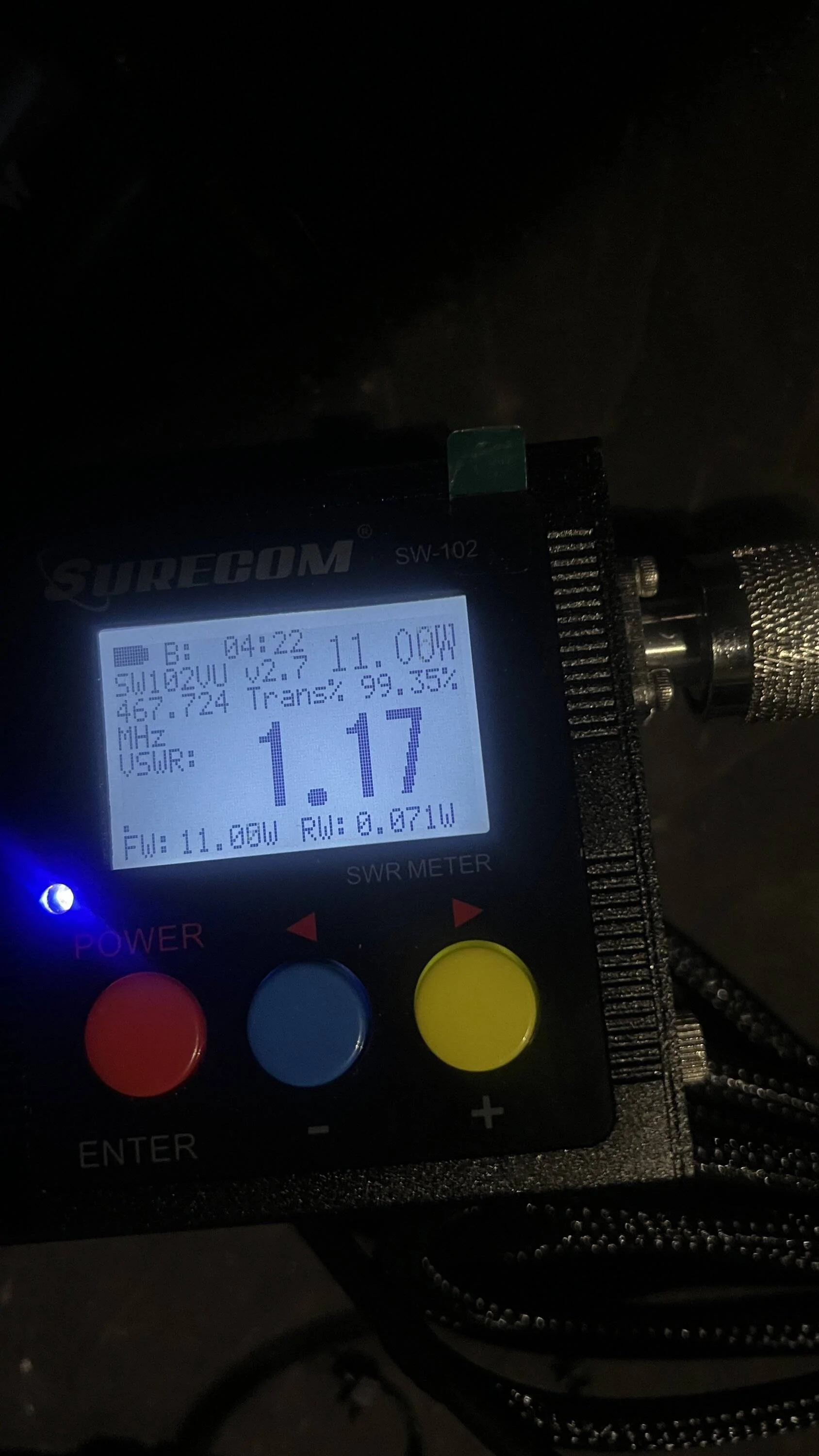
Well I felt I did something wrong so went and checked again. Must have had a connection not fully seated.

Ch 1 was still about the same, but CH 22 was a much higher output wattage (again, no dummy load). But it seemed to fluctuate quite a bit. So maybe some environmental factors? Or maybe I was just in a rush and bumping things around, which should be a cause I dont think.

Still...interesting.
Jeep Gladiator GMRS / CB antenna locations - near A pillar or mid point on hood IMG_9941

Jeep Gladiator GMRS / CB antenna locations - near A pillar or mid point on hood IMG_9942
 

Radio Guy

Well-Known Member
First Name
Mike
Joined
Feb 24, 2021
Threads
6
Messages
716
Reaction score
882
Location
So Cal
Vehicle(s)
2021 Jeep Gladiator Mojave
Occupation
Retired Broadcast Engineer
Its showing a slightly higher VSWR at 467Mhz over 462Mhz so the antenna is a tiny bit too long. But at the worst the match is extremely good so I would not worry about it.

Well I felt I did something wrong so went and checked again. Must have had a connection not fully seated.

Ch 1 was still about the same, but CH 22 was a much higher output wattage (again, no dummy load). But it seemed to fluctuate quite a bit. So maybe some environmental factors? Or maybe I was just in a rush and bumping things around, which should be a cause I dont think.

Still...interesting.
IMG_9941.jpg

IMG_9942.JPG
 

Dougstdig

Well-Known Member
First Name
Doug
Joined
Sep 5, 2017
Threads
26
Messages
1,603
Reaction score
1,560
Location
FL
Vehicle(s)
‘21 JTRD - '08 Dodge Ram 2500 4x4
The only place I found workable SWR’s for the CB antenna. You can mount an antenna anywhere, but if the lack of a proper ground plane prevents correct tuning of the antenna your signal will suck and you can and will damage the finals of the radio.

Jeep Gladiator GMRS / CB antenna locations - near A pillar or mid point on hood 0803C3F2-7CC6-4AB6-909C-4936AC667317


Jeep Gladiator GMRS / CB antenna locations - near A pillar or mid point on hood BE53C904-D8E3-41C0-9CD3-4D99613376E9


Jeep Gladiator GMRS / CB antenna locations - near A pillar or mid point on hood 6B06C442-0DE7-463D-99B7-CF5819615407
 
OP
OP
chorky

chorky

Well-Known Member
First Name
Chad
Joined
Feb 26, 2022
Threads
175
Messages
3,466
Reaction score
3,802
Location
Montana
Website
www.youtube.com
Vehicle(s)
'22JTR, '06 LJ, '06 TJ GE
Build Thread
Link
Occupation
GIS Specialist
The only place I found workable SWR’s for the CB antenna. You can mount an antenna anywhere, but if the lack of a proper ground plane prevents correct tuning of the antenna your signal will suck and you can and will damage the finals of the radio.

0803C3F2-7CC6-4AB6-909C-4936AC667317.jpeg


BE53C904-D8E3-41C0-9CD3-4D99613376E9.jpeg


6B06C442-0DE7-463D-99B7-CF5819615407.jpeg
I have near perfect SWR on the cowl using EVO mounts. Pretty happy about that.

@Radio Guy - might you have any suggestions (that aren't super expensive) for ways to test the actual signal? I recall over on expo portal there was a guy who used some type of equpiment to essentially graph out the signal and what it would look like in terms of a bubble around a vehicle - and said bubble would reach further some ways than others based on the ground plane. Probably some super expensive equipment that I dont want to buy but figured you might know of something.
 

Sponsored

Radio Guy

Well-Known Member
First Name
Mike
Joined
Feb 24, 2021
Threads
6
Messages
716
Reaction score
882
Location
So Cal
Vehicle(s)
2021 Jeep Gladiator Mojave
Occupation
Retired Broadcast Engineer
I have near perfect SWR on the cowl using EVO mounts. Pretty happy about that.

@Radio Guy - might you have any suggestions (that aren't super expensive) for ways to test the actual signal? I recall over on expo portal there was a guy who used some type of equpiment to essentially graph out the signal and what it would look like in terms of a bubble around a vehicle - and said bubble would reach further some ways than others based on the ground plane. Probably some super expensive equipment that I dont want to buy but figured you might know of something.
I'm trained in various types of antenna range measurements and about the best you could do at home would be test signal strength at close range maybe 100ft then swap antennas and test signal strength again. You would want something that can read out well under 1dB of change and a cheap dongle SDR receiver and a laptop might suffice.

If you use the same mount and nothing changes except swapping different antennas on the same mount you can get a real good idea of what antenna is better and by how much. If you are comparing the same type antenna on different mounts in different spots I would want to take a number of measurements around the vehicle like at least four and more is better. You would test mount A then mount B with the receiver and its antenna in the same spot then move the receiver and its antenna and test A and B again, etc. You will find the signal strength varies a lot around the vehicle but using the same type antenna on both mounts will find the better mounting location.

The 100ft distance is a best guess right now because you have to be outside what is called the Near Field where levels will vary in a difficult to predict manner. 100ft at 27MHz with low gain antennas should be safely outside the near field so levels should be believable. The receive antenna can be almost anything from a vertical piece of wire a few feet long to a mobile CB antenna on another vehicle. Its not that critical at close distance.

There is also a ground bounce problem that can skew received levels quite a bit. Ground bounce is where you have the direct path between antennas and a reflection off the ground as a secondary delayed path that is out of phase with the direct path. Since the vehicle and antenna under test is fairly low to the ground and the receive antenna would also be low to the ground hopefully ground bounce will not be a problem and there are some tests to perform to rule that out somewhat.

Anyway, antenna tests like this can be fun and educational and in the end you should be an expert on where to put a CB antenna on a Jeep to get the best range.
 

Radio Guy

Well-Known Member
First Name
Mike
Joined
Feb 24, 2021
Threads
6
Messages
716
Reaction score
882
Location
So Cal
Vehicle(s)
2021 Jeep Gladiator Mojave
Occupation
Retired Broadcast Engineer
The only place I found workable SWR’s for the CB antenna. You can mount an antenna anywhere, but if the lack of a proper ground plane prevents correct tuning of the antenna your signal will suck and you can and will damage the finals of the radio.
Lack of ground plane preventing correct tuning, yes. Signal sucking under those conditions, yes. Damaging your radio with high VSWR, not really. Over the last 40yrs or so I've tried my best to damage a CB by keying down in some cases for hours with no antenna attached, no cable and nothing happens. I've done this probably hundreds of times and never hurt a single one. Its very difficult to damage a modern CB with high VSWR. Early transistor CBs in the 1960s maybe, but not modern stuff.
 
OP
OP
chorky

chorky

Well-Known Member
First Name
Chad
Joined
Feb 26, 2022
Threads
175
Messages
3,466
Reaction score
3,802
Location
Montana
Website
www.youtube.com
Vehicle(s)
'22JTR, '06 LJ, '06 TJ GE
Build Thread
Link
Occupation
GIS Specialist
I'm trained in various types of antenna range measurements and about the best you could do at home would be test signal strength at close range maybe 100ft then swap antennas and test signal strength again. You would want something that can read out well under 1dB of change and a cheap dongle SDR receiver and a laptop might suffice.

If you use the same mount and nothing changes except swapping different antennas on the same mount you can get a real good idea of what antenna is better and by how much. If you are comparing the same type antenna on different mounts in different spots I would want to take a number of measurements around the vehicle like at least four and more is better. You would test mount A then mount B with the receiver and its antenna in the same spot then move the receiver and its antenna and test A and B again, etc. You will find the signal strength varies a lot around the vehicle but using the same type antenna on both mounts will find the better mounting location.

The 100ft distance is a best guess right now because you have to be outside what is called the Near Field where levels will vary in a difficult to predict manner. 100ft at 27MHz with low gain antennas should be safely outside the near field so levels should be believable. The receive antenna can be almost anything from a vertical piece of wire a few feet long to a mobile CB antenna on another vehicle. Its not that critical at close distance.

There is also a ground bounce problem that can skew received levels quite a bit. Ground bounce is where you have the direct path between antennas and a reflection off the ground as a secondary delayed path that is out of phase with the direct path. Since the vehicle and antenna under test is fairly low to the ground and the receive antenna would also be low to the ground hopefully ground bounce will not be a problem and there are some tests to perform to rule that out somewhat.

Anyway, antenna tests like this can be fun and educational and in the end you should be an expert on where to put a CB antenna on a Jeep to get the best range.

What kind of equipment would be needed for something like that? I was kinda toying with the idea of putting a base station CB/GMRS on my house - although I'm probably the only person that would ever be on it in this canyon town of mine..... :-(


As for the signal - I kinda was thinking of how to visualize something like Post 17
https://expeditionportal.com/forum/...-and-relation-to-other-antennas.204431/page-2
 

Radio Guy

Well-Known Member
First Name
Mike
Joined
Feb 24, 2021
Threads
6
Messages
716
Reaction score
882
Location
So Cal
Vehicle(s)
2021 Jeep Gladiator Mojave
Occupation
Retired Broadcast Engineer
What kind of equipment would be needed for something like that? I was kinda toying with the idea of putting a base station CB/GMRS on my house - although I'm probably the only person that would ever be on it in this canyon town of mine..... :-(


As for the signal - I kinda was thinking of how to visualize something like Post 17
https://expeditionportal.com/forum/...-and-relation-to-other-antennas.204431/page-2
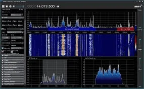
The info at post #17 looks legit. If you get a cheap SDR receiver like the RTL-SDR dongle, about $30 on Amazon and free software it will give you something like the screen shot below on a computer. Its a wide range receiver with spectral display and you can measure differences between signal levels fairly well. This would give you the ability to measure small differences between antennas at a distance using a small antenna on the USB dongle receiver.


Jeep Gladiator GMRS / CB antenna locations - near A pillar or mid point on hood 1675875171229
 
OP
OP
chorky

chorky

Well-Known Member
First Name
Chad
Joined
Feb 26, 2022
Threads
175
Messages
3,466
Reaction score
3,802
Location
Montana
Website
www.youtube.com
Vehicle(s)
'22JTR, '06 LJ, '06 TJ GE
Build Thread
Link
Occupation
GIS Specialist
The info at post #17 looks legit. If you get a cheap SDR receiver like the RTL-SDR dongle, about $30 on Amazon and free software it will give you something like the screen shot below on a computer. Its a wide range receiver with spectral display and you can measure differences between signal levels fairly well. This would give you the ability to measure small differences between antennas at a distance using a small antenna on the USB dongle receiver.


1675875171229.png
K
ok so now that the gmrs is in Lets switch back to cb for a moment. If you recall the antenna I have It has two 10” bases, then the coil, and the whip after. I was looking at it by the jeep today and a little concerned about 20” of base below the coil. Mostly due to the weight. So I took one of the bases off So that the coil is only 10” above the mount (not mounted yet still waiting on coax).

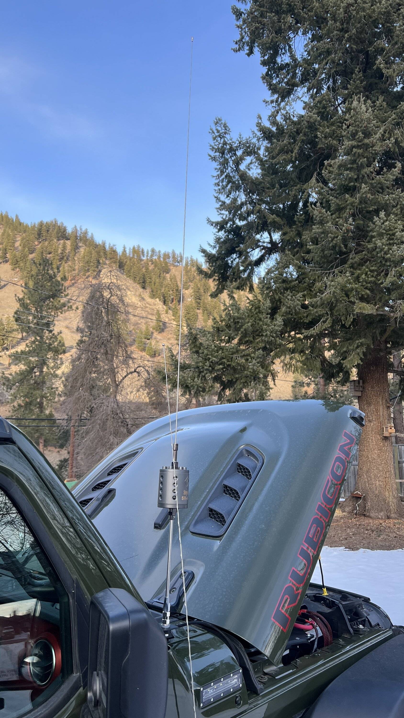
this feels a lot better weight wise but it puts the coil about half way on the windshield frame. Whereas with the full 20” base, the coil is right about at the top of the windshield frame, just barely peaking over the roof.

so my question is, what impacts does this have on signal quality? Is it important for the coil to be above the roofline or does that not matter?

And a follow-on question, if it doesnt matter, would it be of any pro or con to signal quality to remove even the 10” base so that the coil is sitting on the EVO mount itself? (with a plastic spacer of course)

I ask this because as we discussed the gmrs antenna, there is the coil (well thats for 5/8 over 5/8 though) is a little higher than half way on the windshield frame.

But even removing one of the 10” base stems from the cb Im sure will cause some affect to the swr - not sure what though because it is advertised as such, as well as another mag mount option which has the coil sit directly on the mag mount.
 

Sponsored

Radio Guy

Well-Known Member
First Name
Mike
Joined
Feb 24, 2021
Threads
6
Messages
716
Reaction score
882
Location
So Cal
Vehicle(s)
2021 Jeep Gladiator Mojave
Occupation
Retired Broadcast Engineer
ok so now that the gmrs is in Lets switch back to cb for a moment. If you recall the antenna I have It has two 10” bases, then the coil, and the whip after. I was looking at it by the jeep today and a little concerned about 20” of base below the coil. Mostly due to the weight. So I took one of the bases off So that the coil is only 10” above the mount (not mounted yet still waiting on coax).

this feels a lot better weight wise but it puts the coil about half way on the windshield frame. Whereas with the full 20” base, the coil is right about at the top of the windshield frame, just barely peaking over the roof.

so my question is, what impacts does this have on signal quality? Is it important for the coil to be above the roofline or does that not matter?

And a follow-on question, if it doesnt matter, would it be of any pro or con to signal quality to remove even the 10” base so that the coil is sitting on the EVO mount itself? (with a plastic spacer of course)

I ask this because as we discussed the gmrs antenna, there is the coil (well thats for 5/8 over 5/8 though) is a little higher than half way on the windshield frame.

But even removing one of the 10” base stems from the cb Im sure will cause some affect to the swr - not sure what though because it is advertised as such, as well as another mag mount option which has the coil sit directly on the mag mount.
On a center loaded antenna most of the radiation off the antenna is below the coil. I know this doesn't make sense to some but that's how it works. A base loaded antenna with the coil right at the feedpoint will have more loss compared to a center or top load with everything else being equal.

At CB frequencies a full wavelength is about 36ft, so a CB antenna sitting on the hood looking at the front A pillar and roof is like a dump truck looking at a little speed bump in the road. Its not necessarily the size of the antenna up against an obstruction, its the size of the wavelength, so the A pillar and roof is not a big deal at 27MHz. There will be more skewing of the radiation pattern towards the largest area of the hood compared to any obstruction from the A pillar or roof. Plus a Gladiator roof is fiberglass, you only have the A pillars, window frame and roll bar further back that are made of any substantial metal.

The antenna will be more efficient with 20" of mast below the coil and 10" of mast below the coil will be better than the coil sitting on the mount. Make the antenna as long as you can safely use on the mount, also considering hitting things overhead while on the road. Removing 10" of mast below the coil will require lengthening the whip but its not a 1:1 thing, you may only have to lengthen the whip 3" to make up for the missing 10" of mast. If you have extra whip length to play with you will should be able to find a good match with some experimentation.
 
OP
OP
chorky

chorky

Well-Known Member
First Name
Chad
Joined
Feb 26, 2022
Threads
175
Messages
3,466
Reaction score
3,802
Location
Montana
Website
www.youtube.com
Vehicle(s)
'22JTR, '06 LJ, '06 TJ GE
Build Thread
Link
Occupation
GIS Specialist
On a center loaded antenna most of the radiation off the antenna is below the coil. I know this doesn't make sense to some but that's how it works. A base loaded antenna with the coil right at the feedpoint will have more loss compared to a center or top load with everything else being equal.

At CB frequencies a full wavelength is about 36ft, so a CB antenna sitting on the hood looking at the front pillar and roof is like a dump truck looking at a little speed bump in the road. Its not necessarily the size of the antenna up against an obstruction, its the size of the wavelength, so the front pillar and roof is not a big deal at 27MHz. There will be more skewing of the radiation pattern towards the largest area of the hood compared to any obstruction from the pillar or roof. Plus a Gladiator roof is fiberglass, you only have the front pillars, window frame and roll bar further back that are made of any substantial metal.

The antenna will be more efficient with 20" of mast below the coil and 10" of mast below the coil will be better than the coil sitting on the mount. Make the antenna as long as you can safely use on the mount, also considering hitting things overhead while on the road. Removing 10" of mast below the coil will require lengthening the whip but its not a 1:1 thing, you may only have to lengthen the whip 3" to make up for the missing 10" of mast. If you have extra whip length to play with you will should be able to find a good match with some experimentation.
Hmm interesting. I thought I read many years ago that the purpose of a center load is to raise the radiating center above obstructions. Especially considering other options, like one of the President antennas, being a base load, was about 20 bucks or so more expensive. But that might make sense though because now that I think about it I think the standard fire stick is a top load.....

I have a Rubi - so pretty sure my hood is steel, but I'll check it with a magnet tomorrow.

Would there realistically be any measurable loss or difference with the 10" base vs 20" base? I think the 10" base would be ok. But the 20" base just seems to exponentially add some lateral force. I could try it out...but seeing as how the cowl bolts are not nearly as substantial as I thought before taking them off, it has me slightly concerned of hitting a stiff branch or bouncing around hard.

I am not super concerned about total height. It's still going to be shorter than the 108" on my TJ.....

I will be really curious to see what the SWR readings are. It came pre-assembled with both 10" of stainless below the coil, so the 20" of mast as you suggested...but with the whip attached. So understanding your comment, that would mean that the whip, with 20" of mast, would need to be cut. However, with just the 10", it might be near perfect. Just a wild assumption based on the description of the antenna from the company. I think I will try it with the 10" of mast first just to see what the SWR reads, and because I took the other 10" of stainless off already to compare the two.

But this is something to think about - whether or not I think it will be ok with 20"...or if that's too much for the mount. Not really sure to be honest. Might just be trial and error.
 

Radio Guy

Well-Known Member
First Name
Mike
Joined
Feb 24, 2021
Threads
6
Messages
716
Reaction score
882
Location
So Cal
Vehicle(s)
2021 Jeep Gladiator Mojave
Occupation
Retired Broadcast Engineer
Hmm interesting. I thought I read many years ago that the purpose of a center load is to raise the radiating center above obstructions. Especially considering other options, like one of the President antennas, being a base load, was about 20 bucks or so more expensive. But that might make sense though because now that I think about it I think the standard fire stick is a top load.....

I have a Rubi - so pretty sure my hood is steel, but I'll check it with a magnet tomorrow.

Would there realistically be any measurable loss or difference with the 10" base vs 20" base? I think the 10" base would be ok. But the 20" base just seems to exponentially add some lateral force. I could try it out...but seeing as how the cowl bolts are not nearly as substantial as I thought before taking them off, it has me slightly concerned of hitting a stiff branch or bouncing around hard.

I am not super concerned about total height. It's still going to be shorter than the 108" on my TJ.....

I will be really curious to see what the SWR readings are. It came pre-assembled with both 10" of stainless below the coil, so the 20" of mast as you suggested...but with the whip attached. So understanding your comment, that would mean that the whip, with 20" of mast, would need to be cut. However, with just the 10", it might be near perfect. Just a wild assumption based on the description of the antenna from the company. I think I will try it with the 10" of mast first just to see what the SWR reads, and because I took the other 10" of stainless off already to compare the two.

But this is something to think about - whether or not I think it will be ok with 20"...or if that's too much for the mount. Not really sure to be honest. Might just be trial and error.
Using the full 20" mast below the coil will put out a measurably better signal than using a 10" mast. It may only be a dB or so and a fraction of an S unit on the receive end, but a single S unit is supposed to be a 6dB change in signal level. If they give you the option to use one or both masts I would think the whip is long enough to work with one mast and several inches of whip might be sitting down inside the coil or the upper hollow mast if there is one so its compatible with both lower masts.

For the type of antenna we are discussing, starting at the feedpoint will be the lowest impedance and it goes higher as you go up the antenna until you reach the tip where it will be 2 to 3 thousand ohms. Maximum radiation occurs at lower impedance where the current is higher and the voltage is lower, so the lowest portion of the antenna radiates more than the middle or top. The loading coil is only there to shorten the antenna from about 9ft tall to something shorter. It can be placed anywhere on the antenna but the center is a pretty good place to put it for many technical and mechanical reasons.

If you could measure the impedance along a full 9ft 1/4 wave whip it would be very predictable along the entire length. An antenna that is shortened using a loading coil is not as easy to predict but usually the top whip doesn't radiate that much but the voltage is very high there and the electric field is much stronger so it can light up a fluorescent light bulb near the top where it won't light up near the bottom. But its not just the electric field that gets your signal across town.
 
OP
OP
chorky

chorky

Well-Known Member
First Name
Chad
Joined
Feb 26, 2022
Threads
175
Messages
3,466
Reaction score
3,802
Location
Montana
Website
www.youtube.com
Vehicle(s)
'22JTR, '06 LJ, '06 TJ GE
Build Thread
Link
Occupation
GIS Specialist
Using the full 20" mast below the coil will put out a measurably better signal than using a 10" mast. It may only be a dB or so and a fraction of an S unit on the receive end, but a single S unit is supposed to be a 6dB change in signal level. If they give you the option to use one or both masts I would think the whip is long enough to work with one mast and several inches of whip might be sitting down inside the coil or the upper hollow mast if there is one so its compatible with both lower masts.

For the type of antenna we are discussing, starting at the feedpoint will be the lowest impedance and it goes higher as you go up the antenna until you reach the tip where it will be 2 to 3 thousand ohms. Maximum radiation occurs at lower impedance where the current is higher and the voltage is lower, so the lowest portion of the antenna radiates more than the middle or top. The loading coil is only there to shorten the antenna from about 9ft tall to something shorter. It can be placed anywhere on the antenna but the center is a pretty good place to put it for many technical and mechanical reasons.

If you could measure the impedance along a full 9ft 1/4 wave whip it would be very predictable along the entire length. An antenna that is shortened using a loading coil is not as easy to predict but usually the top whip doesn't radiate that much but the voltage is very high there and the electric field is much stronger so it can light up a fluorescent light bulb near the top where it won't light up near the bottom. But its not just the electric field that gets your signal across town.

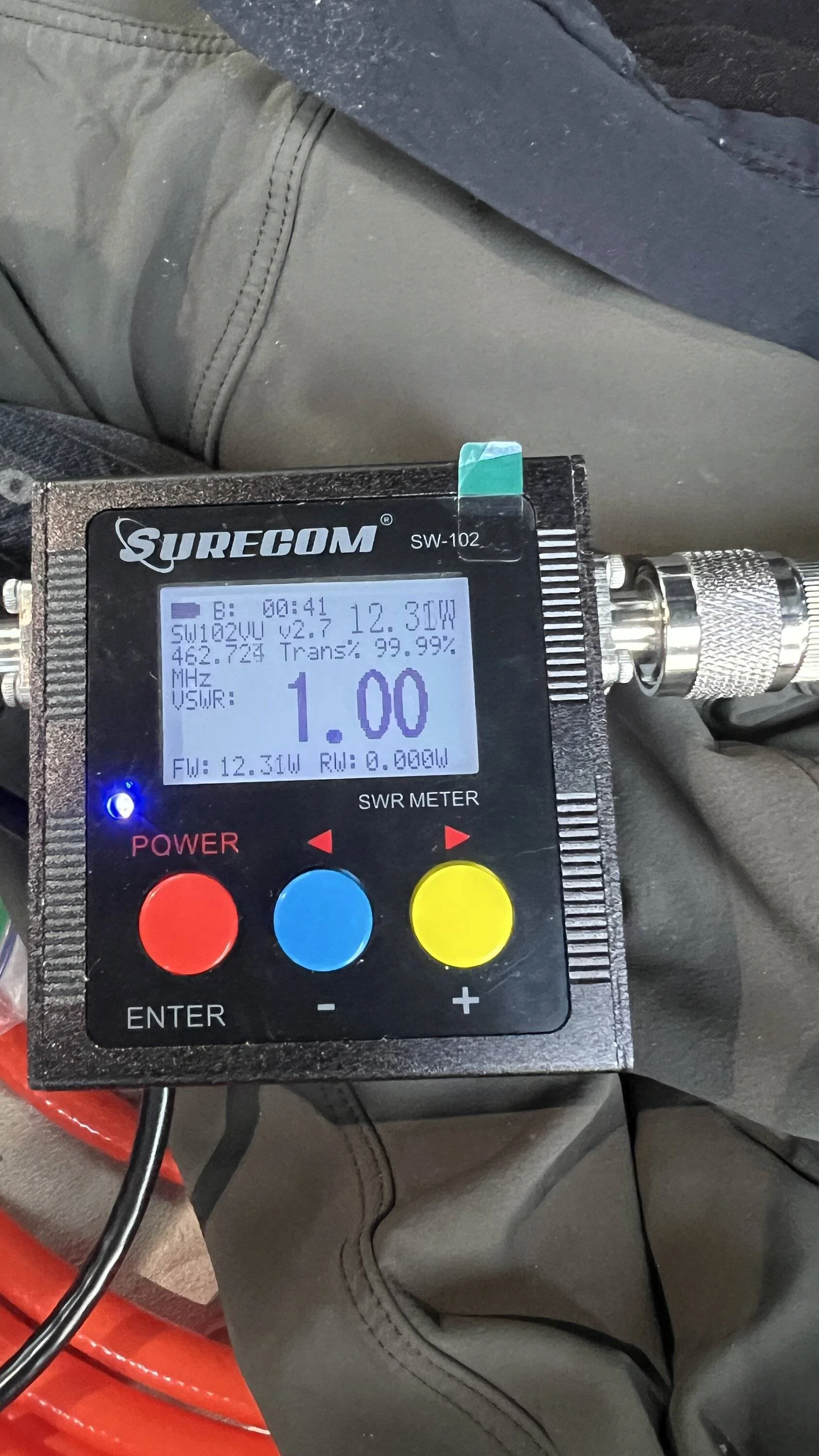
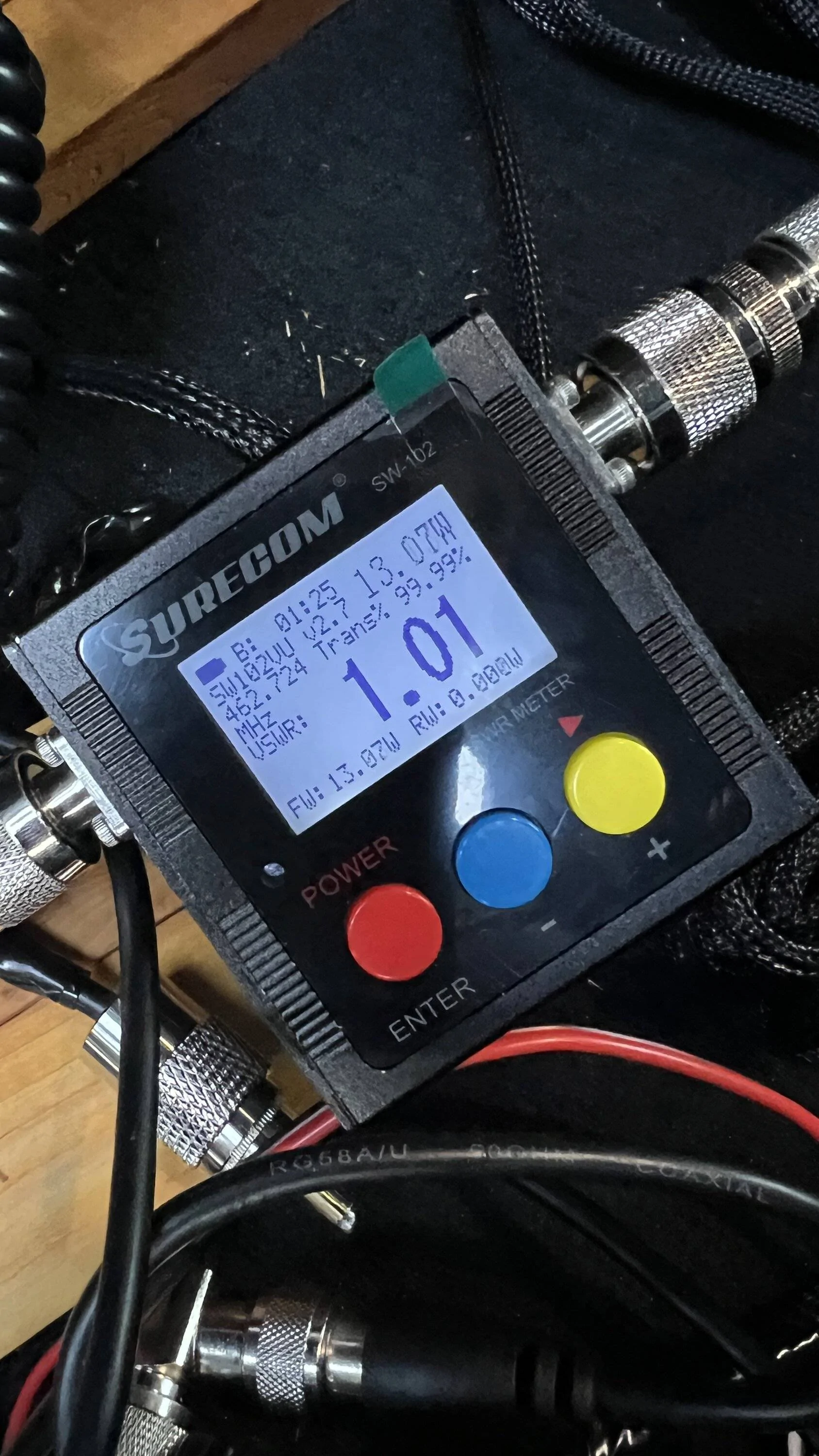
Parts came in yesterday. I re-checked the GMRS with a dummy load, and again just to the antenna. Here are the results - just checking on CH 22. Dummy first, antenna second.
Jeep Gladiator GMRS / CB antenna locations - near A pillar or mid point on hood IMG_9984

Jeep Gladiator GMRS / CB antenna locations - near A pillar or mid point on hood IMG_9985

I think I can be satisfied with these results. Now just need to find someone willing to do some functional testing in my area!

So next was checking continuity of the CB antenna. After soldering the PL connector (I did not yet cut to length as the location might move for the radios a few feet) I found continuity to be 0.00 between coax center wire and the antenna base, and continuity to be about 0.03 between the outside of the PL connector and a body ground.

I ended up using just one of the 10" masts. 20" was great in that it actually put half of the coil above the windshield frame. But wiggling it around it seemed to put a lot of extra force on the EVO bracket. I wish threre was a stronger bracket that tied into both of those top bolts and the windshield bolt. But seeing as that windshield bolt (or cover bolt actually) is just either thick plastic or aluminum, I didn't want that much force to be placed on it....
Jeep Gladiator GMRS / CB antenna locations - near A pillar or mid point on hood IMG_9986


So SWR readings next. I did have to cut the whip some. Probably 3/4 to 1 inch in total. Before doing that I did check SWR readings with both 10" masts, for a total of 20, and I would have had to cut the antenna anyway, so I didn't feel so bad. The antenna sits 2-3 inches inside that top shaft, so if I opted later to extend the mast another 10" then there should be plenty of whip to adjust...

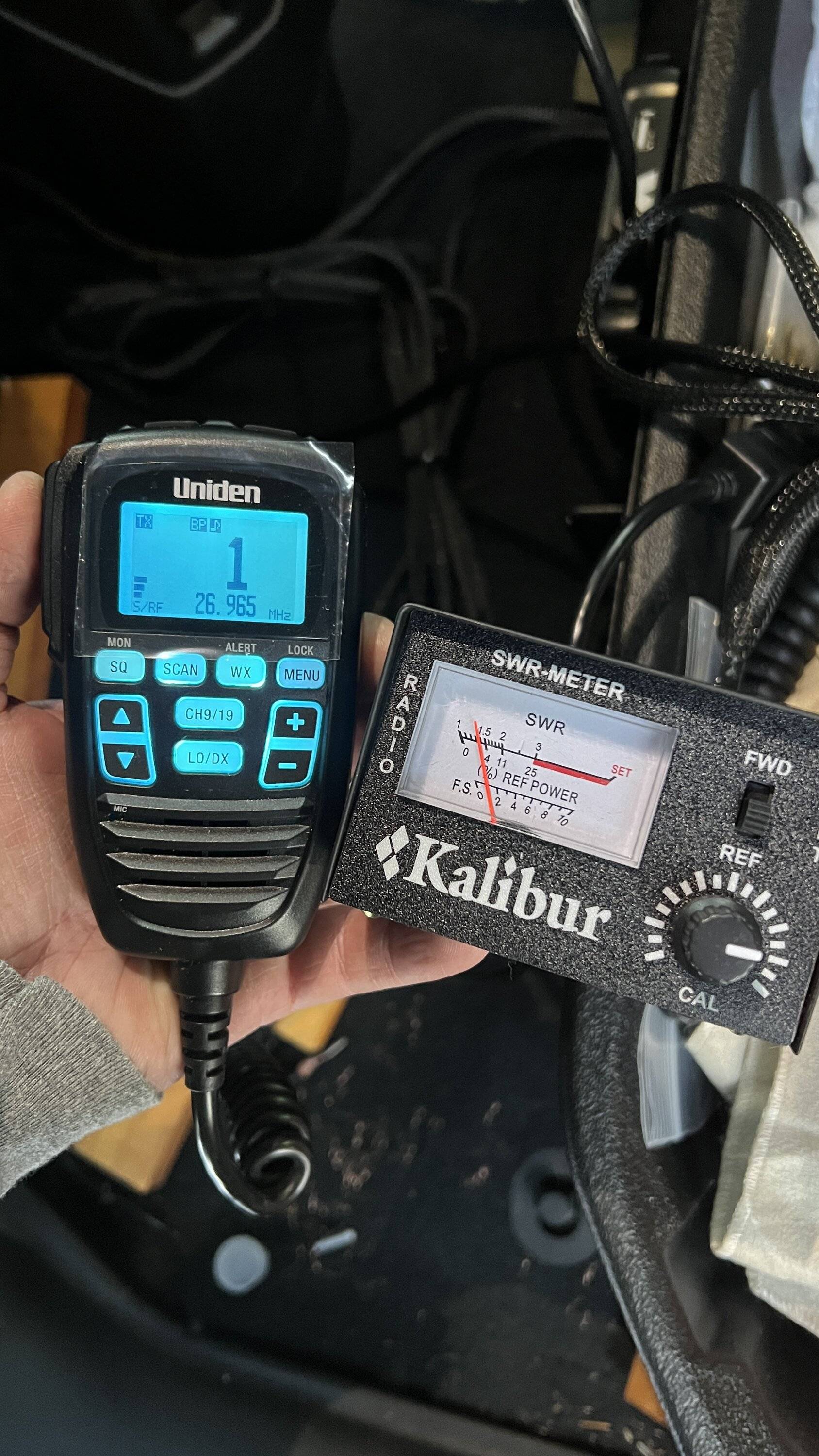
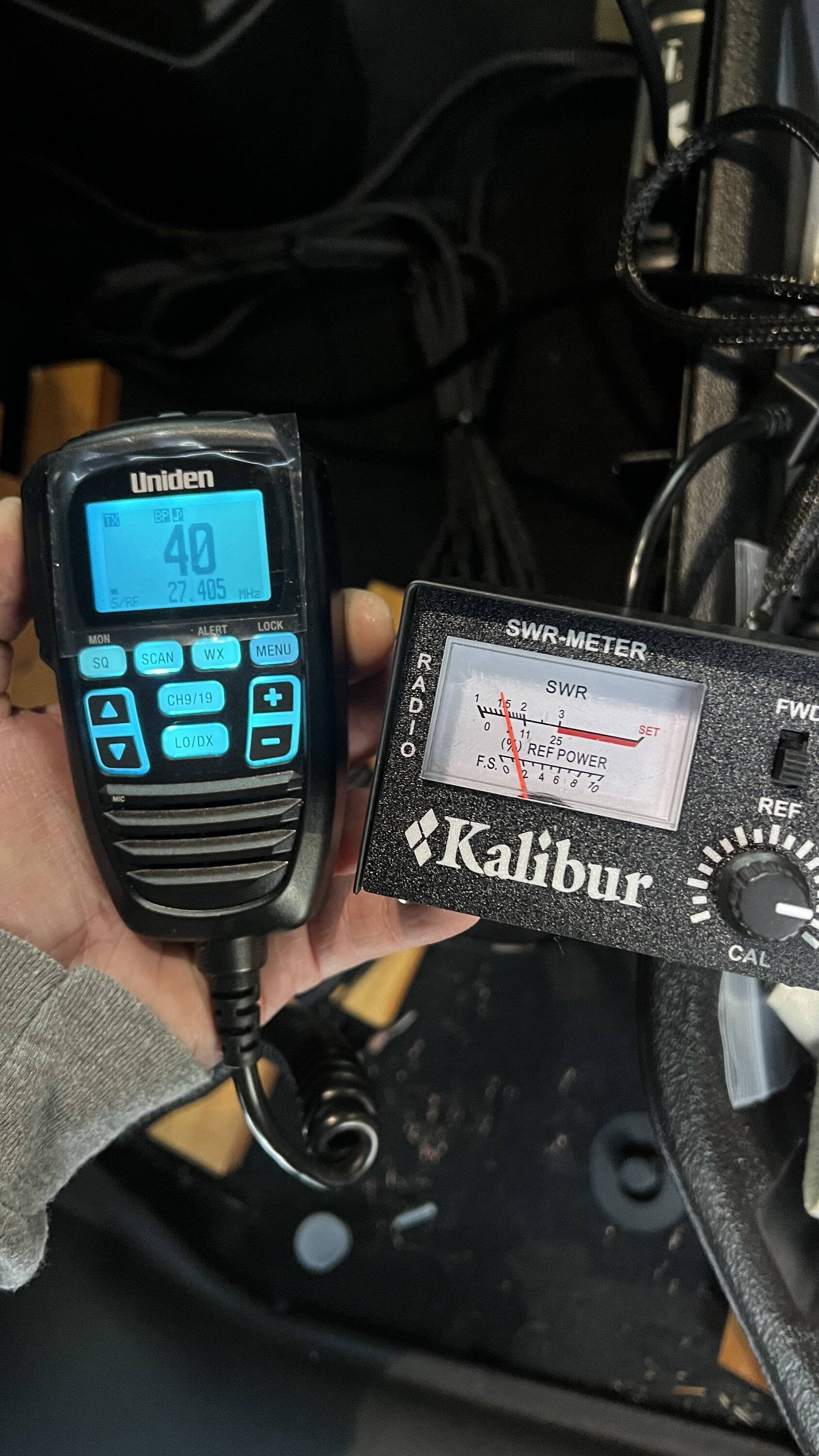
So SWR reading's aren't as good as I want, and I think it's due to the resistance in the ground, from the coax outermost wire to a body ground. I have a feeling the EVO mount itself is struggling to have good contact with metal, and that's where the majority of the resistance is. Since I need to cut the coax to length later, I didn't want to spend a whole lot of time on it and it was cold out. But the SWR's are within manufacturer spec.

I was hoping to at least get CH 1 down at or below 1.25 - but this is decent I think?

Jeep Gladiator GMRS / CB antenna locations - near A pillar or mid point on hood IMG_9988

Jeep Gladiator GMRS / CB antenna locations - near A pillar or mid point on hood IMG_9989


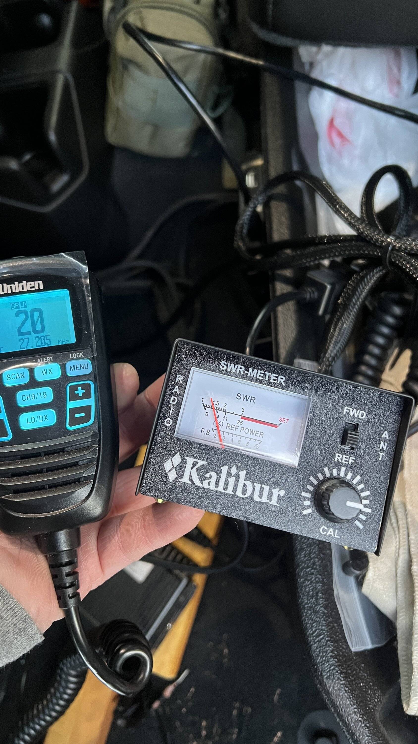
And as per Stryker, CH 20 is at or below 1.5
Jeep Gladiator GMRS / CB antenna locations - near A pillar or mid point on hood IMG_9987


One thing that bothers me is on the mic screen, on the left, the owners manual doesn't talk at all about what that S/RF meter is all about. You can see on CH 1 it's at 3 bars, and CH 40 is at 1 bar, out of 7 bars possible. I'm assuming this is just your standard receiving and transmitting strength - and if that's true then my power output is very poor.....Not sure what could impact that. Any suggestions?
 

Radio Guy

Well-Known Member
First Name
Mike
Joined
Feb 24, 2021
Threads
6
Messages
716
Reaction score
882
Location
So Cal
Vehicle(s)
2021 Jeep Gladiator Mojave
Occupation
Retired Broadcast Engineer
Parts came in yesterday. I re-checked the GMRS with a dummy load, and again just to the antenna. Here are the results - just checking on CH 22. Dummy first, antenna second.
IMG_9984.jpg

IMG_9985.jpg

I think I can be satisfied with these results. Now just need to find someone willing to do some functional testing in my area!

So next was checking continuity of the CB antenna. After soldering the PL connector (I did not yet cut to length as the location might move for the radios a few feet) I found continuity to be 0.00 between coax center wire and the antenna base, and continuity to be about 0.03 between the outside of the PL connector and a body ground.

I ended up using just one of the 10" masts. 20" was great in that it actually put half of the coil above the windshield frame. But wiggling it around it seemed to put a lot of extra force on the EVO bracket. I wish threre was a stronger bracket that tied into both of those top bolts and the windshield bolt. But seeing as that windshield bolt (or cover bolt actually) is just either thick plastic or aluminum, I didn't want that much force to be placed on it....
IMG_9986.jpg


So SWR readings next. I did have to cut the whip some. Probably 3/4 to 1 inch in total. Before doing that I did check SWR readings with both 10" masts, for a total of 20, and I would have had to cut the antenna anyway, so I didn't feel so bad. The antenna sits 2-3 inches inside that top shaft, so if I opted later to extend the mast another 10" then there should be plenty of whip to adjust...

So SWR reading's aren't as good as I want, and I think it's due to the resistance in the ground, from the coax outermost wire to a body ground. I have a feeling the EVO mount itself is struggling to have good contact with metal, and that's where the majority of the resistance is. Since I need to cut the coax to length later, I didn't want to spend a whole lot of time on it and it was cold out. But the SWR's are within manufacturer spec.

I was hoping to at least get CH 1 down at or below 1.25 - but this is decent I think?

IMG_9988.jpg

IMG_9989.jpg


And as per Stryker, CH 20 is at or below 1.5
IMG_9987.jpg


One thing that bothers me is on the mic screen, on the left, the owners manual doesn't talk at all about what that S/RF meter is all about. You can see on CH 1 it's at 3 bars, and CH 40 is at 1 bar, out of 7 bars possible. I'm assuming this is just your standard receiving and transmitting strength - and if that's true then my power output is very poor.....Not sure what could impact that. Any suggestions?
Looks very good overall. The CB SWR readings show more than likely the whip is a bit too long. If there is enough whip below the set screw where you could trim off another 1/2" or so it should be safe to do so. But if nothing changes its really fine, nothing to worry about. A 1.5:1 or less SWR is good.
Sponsored


Top