RealMcCoy
Well-Known Member
- First Name
- Kevin
- Joined
- Jan 23, 2020
- Threads
- 1
- Messages
- 74
- Reaction score
- 59
- Location
- Fayetteville
- Vehicle(s)
- 2020 Jeep Gladiator JT
- Occupation
- Retired
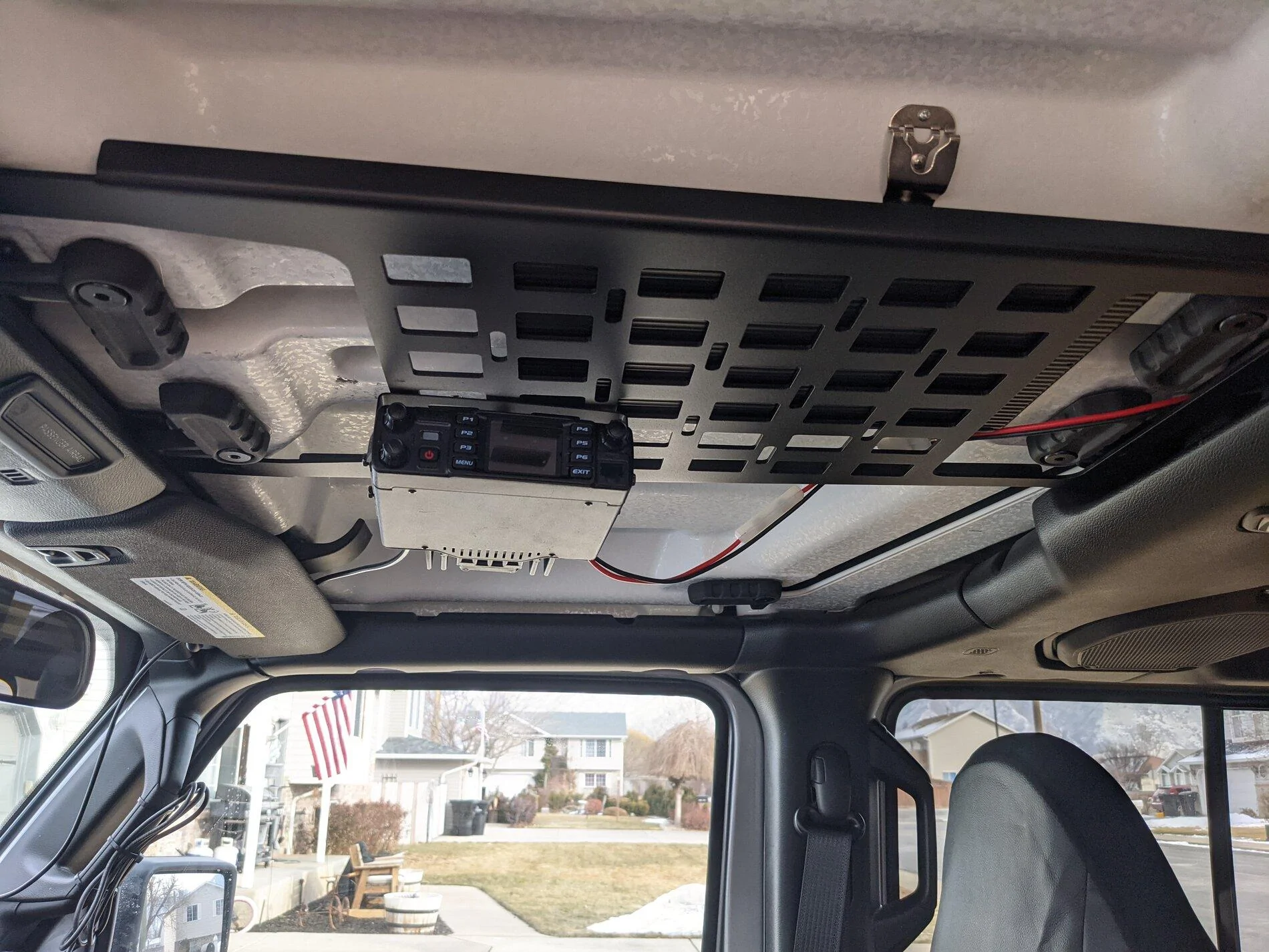
Wow, you have my empathy for sure. S*it happens. Thank you for posting this F*ck up. I may have done the same thing soon, Mine is in route!I have a 2021 Jeep Gladiator Sport and I wanted to mount a ham radio. So I ordered an Overhead MOLLE Panel from JcrOffroad and mounted it tonight. Unfortunately I've had nothing but trouble ever since.
The symptoms I noticed:
- It didn't detect my key fob so I had to push the start button with the key fob.
- The windshield wipers turn on when the ignition is running and nothing I can do will turn the wipers off.
- The turn signals don't respond.
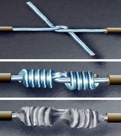
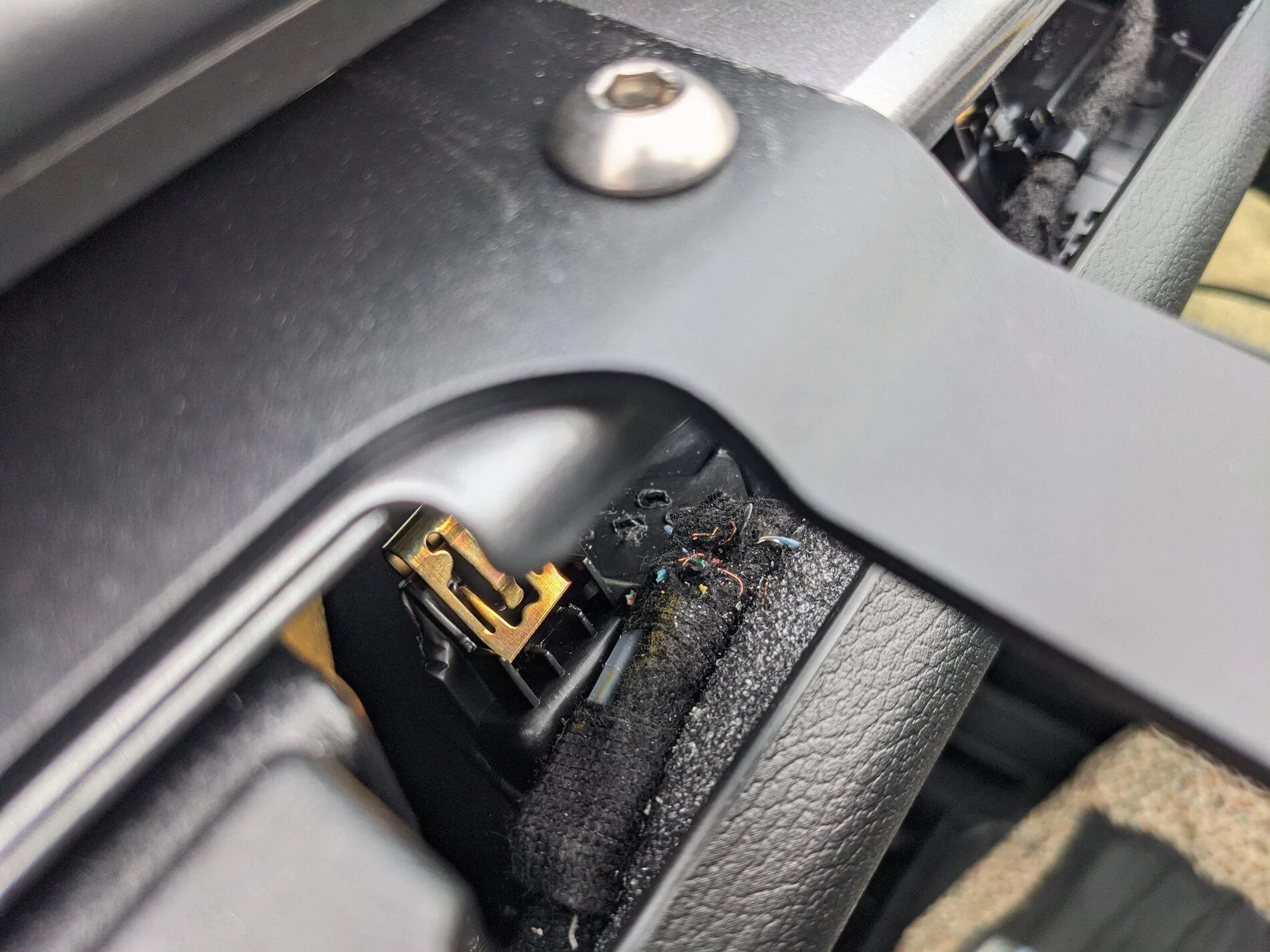
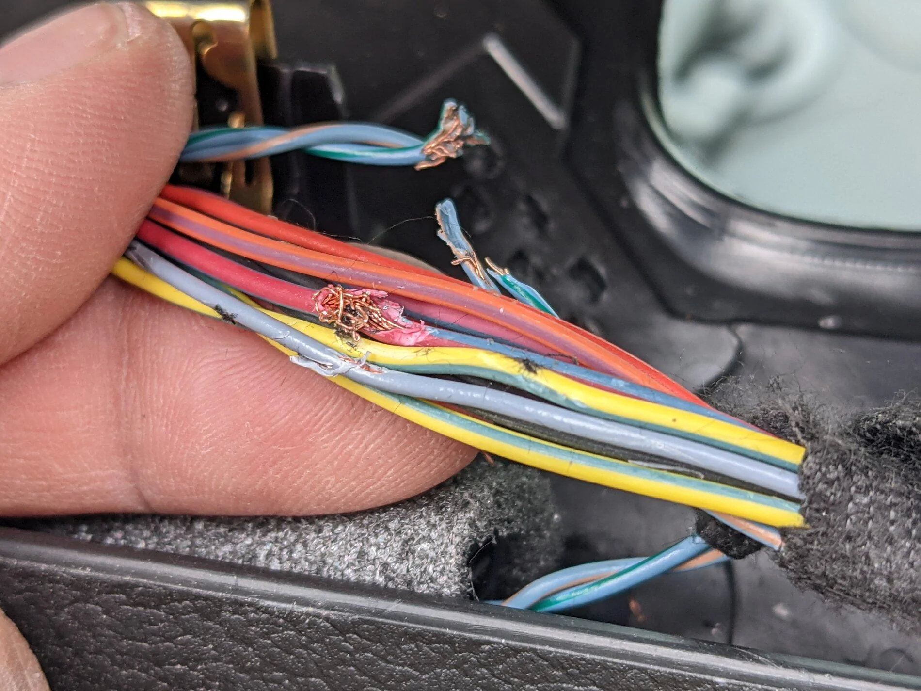
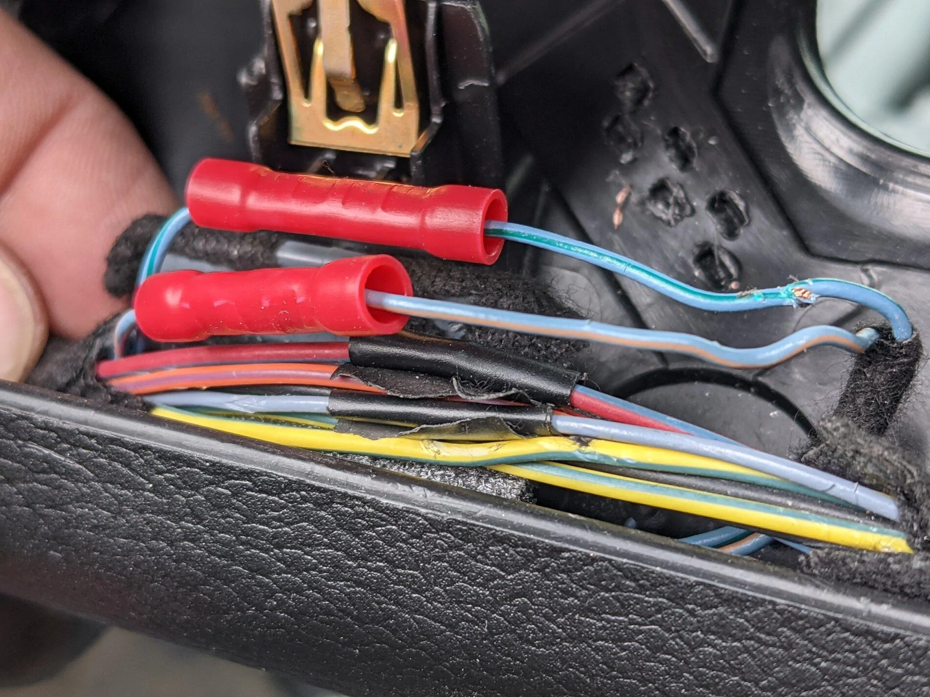
I eventually discovered I had accidentally drilled through some wires. I did my best to splice the wires back together, but the same symptoms persist.
Some things I've tried:
- Disconnect the two batteries for 20 minutes, apply the brake, then reconnect.
- Check the fuses for any signs of a failure.
Please advise.

Seriously, appreciate you posting this.
Sponsored
") Keep a cool head, keep posting info, and you’ll get through this!
Keep a cool head, keep posting info, and you’ll get through this!