OP
OP
Flanders
Well-Known Member
- Thread starter
- #136
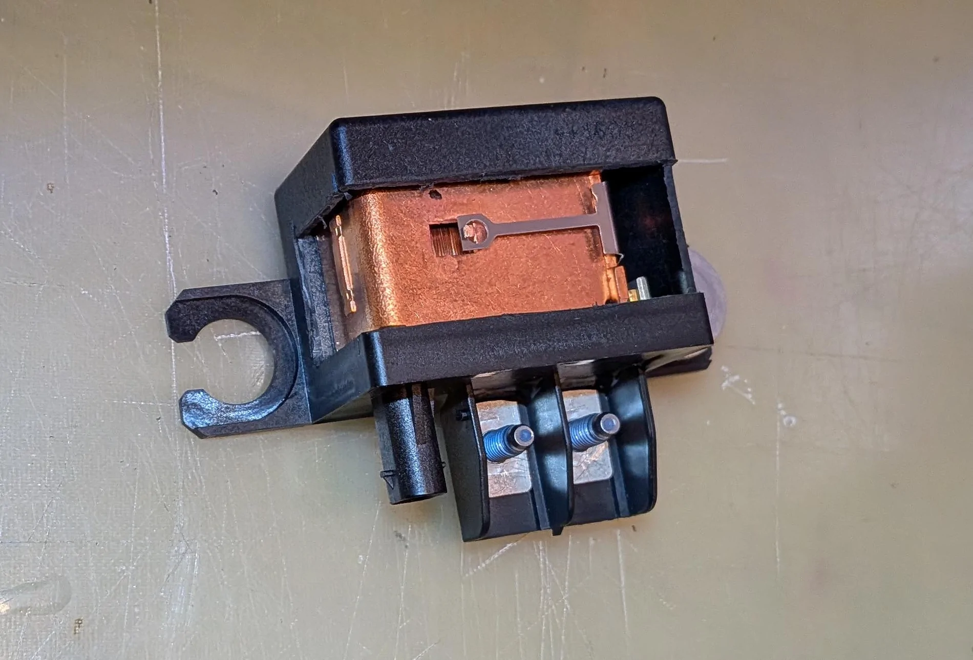
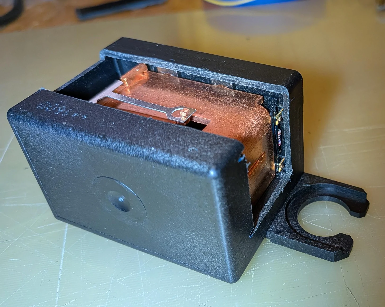
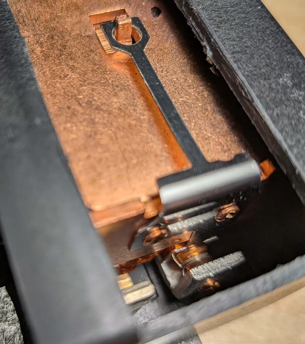
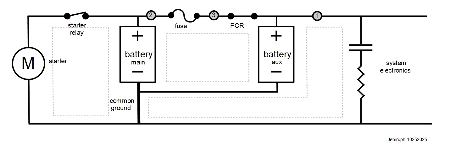
A real nerd should know the resistance across N1 and N2 on the PDC. The only path for current from N1 to N2 goes through the PCR, which is normally closed (conducting).
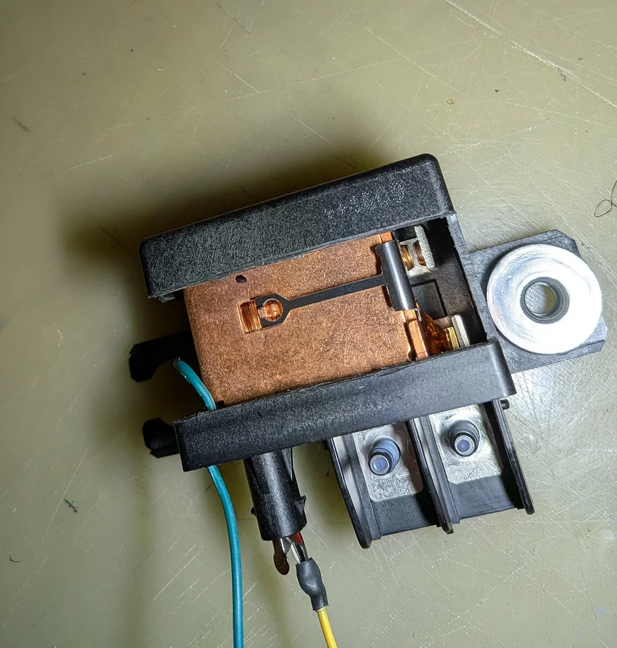
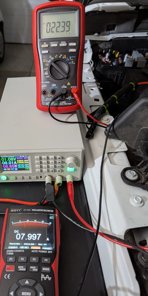
Let's put some current through it and check the voltage drop:

Apply Ohm's law: 22.39mV / 7.997A = 2.8 millohms.
The voltage during cold starts can be read from the scope traces I posted in this thread a year ago:
Z is the oscilloscope ground lead
Blue is the voltage from Z to N1
Yellow is the voltage from Z to N2
Kirchhoff's Voltage law says blue minus yellow equals the voltage from N2 to N1 (Z cancels out). Both cold starts show this to be about 0.75V immediately after the starter relay closes.
That means the AUX supplied over 250A to the starter for a few milliseconds. I didn't think the little guy had it in him.
It also means I was wrong when, in the very first post of this thread, I estimated the resistance at 7.5 milliohms and no less than half that. Turns out it was closer to one-third.
Let's put some current through it and check the voltage drop:
Apply Ohm's law: 22.39mV / 7.997A = 2.8 millohms.
The voltage during cold starts can be read from the scope traces I posted in this thread a year ago:
Z is the oscilloscope ground lead
Blue is the voltage from Z to N1
Yellow is the voltage from Z to N2
Kirchhoff's Voltage law says blue minus yellow equals the voltage from N2 to N1 (Z cancels out). Both cold starts show this to be about 0.75V immediately after the starter relay closes.
That means the AUX supplied over 250A to the starter for a few milliseconds. I didn't think the little guy had it in him.
It also means I was wrong when, in the very first post of this thread, I estimated the resistance at 7.5 milliohms and no less than half that. Turns out it was closer to one-third.
Sponsored

")