Sponsored

Charging amperage - based on voltage levels

OP
OP
chorky

chorky

Well-Known Member
First Name
Chad
Joined
Feb 26, 2022
Threads
175
Messages
3,466
Reaction score
3,801
Location
Montana
Website
www.youtube.com
Vehicle(s)
'22JTR, '06 LJ, '06 TJ GE
Build Thread
Link
Occupation
GIS Specialist
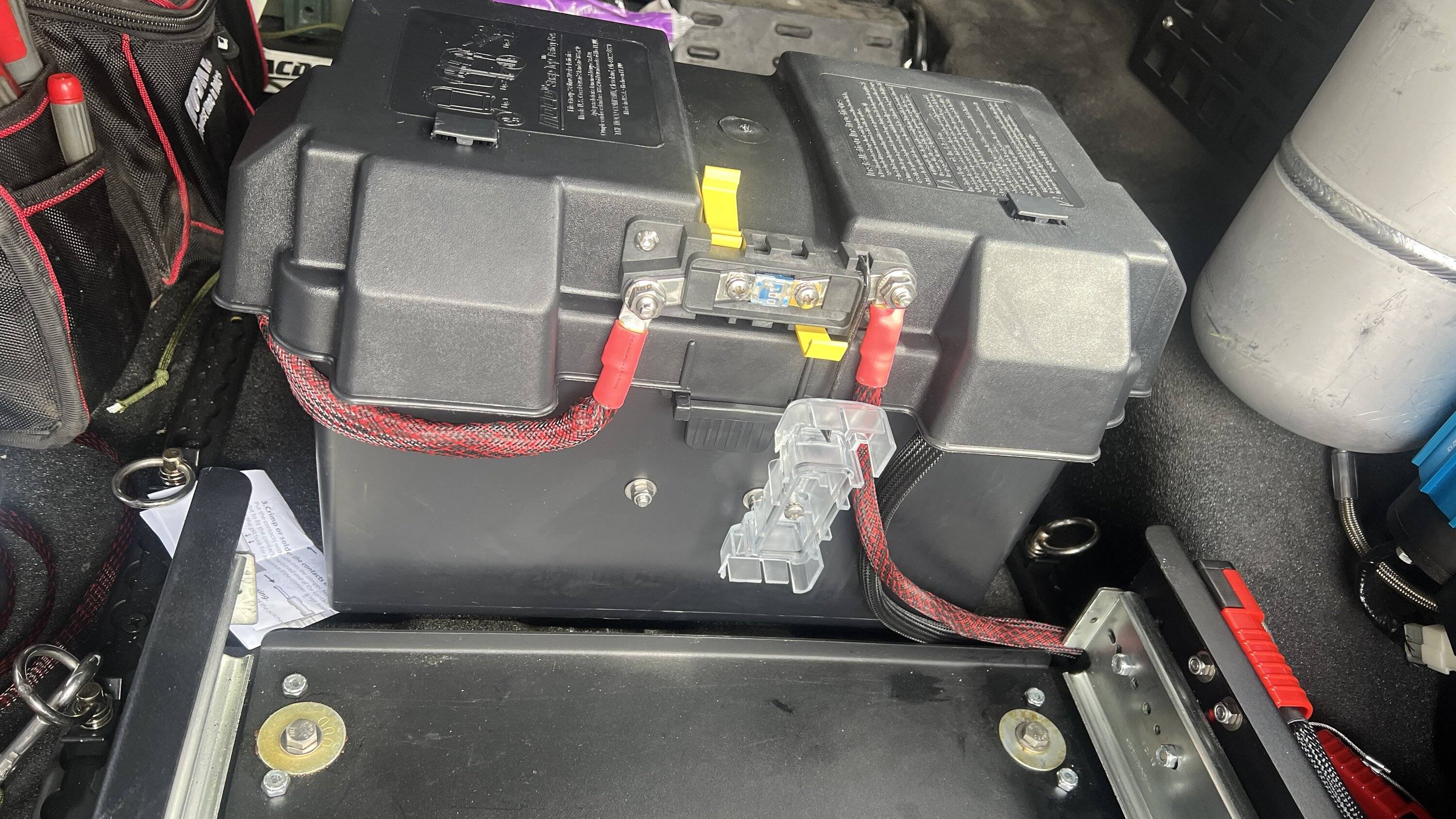
Reviving this thread. I currently have one of the above batteries in the bed, connected to the rest of my system (on build thread) via 100a fuse and Anderson connection.
Jeep Gladiator Charging amperage - based on voltage levels IMG_0351


I want to add a second battery in the bed.
The question is
  • is it better to tie both batteries together first via a power block, and then to an Anderson connection - so only one Anderson connection
  • Or is it better for each battery to have it's own Anderson connection that then goes to the main power block (doubling wires basically)
  • Either way I will be relocating the 100a fuse to be closer to the power system in the bed, and will add a second 100A fuse for the second aux battery. And in fact I likely will swap the 100a fuses out for a 80 or even 60a fuse as there is nothing these batteries need to provide 100a for.
Here is a old work in progress photo for reference. Bed aux battery is tied directly into the blue sea switch, and the blue sea switch #2 connected to the in bed aux battery so I can 1) use main battery only, 2) use aux bed battery only (3) use both together and in turn charge aux batteries if/when they are low. So I am just adding another battery to this existing system.
Jeep Gladiator Charging amperage - based on voltage levels IMG_0292
Sponsored


Mr._Bill

Well-Known Member
First Name
Bill
Joined
Jul 22, 2019
Threads
38
Messages
6,646
Reaction score
7,727
Location
North Las Vegas, NV
Vehicle(s)
2023 Gladiator High Altitude - 2013 Nissan Leaf SV
Vehicle Showcase
1
All your batteries should be AGM, since that is what the Jeep electrical system was designed to be used with.

I would get two matching batteries for the bed and parallel them together. Use a Smart Isolator to connect the bed batteries to the electrical system. This will charge the batteries when the engine is running, and isolate them to prevent discharge of the starting battery when the engine is off.

Since you already have a Genesis system, you could take advantage of the Smart Isolator it uses and parallel the bed batteries with the second battery up front. This will provide a large storage bank to draw from, and protect the starting battery from discharge.

The use of the Anderson connectors is your wiring preference. I would have at least one between the front and back for isolation when doing service.

The fuse between the front and back should be sized to match the draw the wiring can safely handle. I would use the manual disconnect switch between the front and back to separate them for high draw activity like running a winch or jump starting another vehicle.
 

Minty JL

Well-Known Member
First Name
Jeremy
Joined
May 15, 2019
Threads
25
Messages
4,798
Reaction score
7,618
Location
Ft Meade, MD - AOR
Vehicle(s)
23 JTM - 19 JLUR - 22 Compass LTD - 04 355 ZQ8
Occupation
USA(R), DoD - Dirty Contractor
I'm sure Bill will correct me if I'm wrong, but all of the batteries should be charging at the same rate (voltage/amperage) as all of the batteries are inline, the flow through effect.

In the past while working in Electronic Warfare I had to come up with a lot of last minute power needs while running our equipment and new equipment that was in testing for DoD. I not only had to do a lot of proof of concept, but provide the Field Service Reps with measured performance on paper that would coincide with the equipment's power requirements within the high and low thresholds.

I was taking Suburban's and Silverado's straight from the airport rentals and adapt a 12v solution. A few Optima red tops, 4ga wire, terminals and some measurements and it all worked.

My secondary and third batteries were being run directly of the trucks primary battery. Voltage and charging rates where all measured, at the Alternator and all of the batteries. As long as I could run the truck at idle even with the AC on I was retaining the same charging rate across all 3 batteries within a .1xx voltage.
 
OP
OP
chorky

chorky

Well-Known Member
First Name
Chad
Joined
Feb 26, 2022
Threads
175
Messages
3,466
Reaction score
3,801
Location
Montana
Website
www.youtube.com
Vehicle(s)
'22JTR, '06 LJ, '06 TJ GE
Build Thread
Link
Occupation
GIS Specialist
All your batteries should be AGM, since that is what the Jeep electrical system was designed to be used with.

I would get two matching batteries for the bed and parallel them together. Use a Smart Isolator to connect the bed batteries to the electrical system. This will charge the batteries when the engine is running, and isolate them to prevent discharge of the starting battery when the engine is off.

Since you already have a Genesis system, you could take advantage of the Smart Isolator it uses and parallel the bed batteries with the second battery up front. This will provide a large storage bank to draw from, and protect the starting battery from discharge.

The use of the Anderson connectors is your wiring preference. I would have at least one between the front and back for isolation when doing service.

The fuse between the front and back should be sized to match the draw the wiring can safely handle. I would use the manual disconnect switch between the front and back to separate them for high draw activity like running a winch or jump starting another vehicle.
The system is already well set up. no concern for charging methods or idolators. All of that is in place. The main wire to the bed is fused under the hood at 100a for the 4ga wire. I can put the under hood isolator in an open state from in the cab - no mechanical turning of knobs here. Bed batteries will be the same. Each battery is capable of a max bulk current charge rate of 40a, so 80a total leaving sufficient room for charging and continued use of fridge and compressor. The batteries are again fused in the bed to 60a each Since power draw should be no more than 50 at any given time. And the blue sea switch in the bed can isolate the batteries from the wiring to under the hood for any maintenance needs so al that safety is there.

The only thing I am contemplating is the connection between the in bed distribution block to the batteries and if I want one anderson connection for both bed batteries or for each battery to have its own. It's probably more a personal preference thing though than anything else. I am leaning toward each battery having its own connector.
 
Last edited:

Mr._Bill

Well-Known Member
First Name
Bill
Joined
Jul 22, 2019
Threads
38
Messages
6,646
Reaction score
7,727
Location
North Las Vegas, NV
Vehicle(s)
2023 Gladiator High Altitude - 2013 Nissan Leaf SV
Vehicle Showcase
1
the system is already well set up. The only thing i am contemplating is having one anderson connection for both bed batteries or for each battery to have its own. It's probably more a personal preference thing though than anything else.
Yes, that would be a personal preference. If you plan to remove the batteries for winter storage, I would put a connector on each one. If they will stay in place until service or replacement is needed, then one is probably all that's needed.
 

Sponsored

ShadowsPapa

Well-Known Member
First Name
Bill
Joined
Oct 12, 2019
Threads
247
Messages
40,442
Reaction score
53,860
Location
Runnells, Iowa
Vehicle(s)
'25 JTMX, '23 JLU 4xe, '82 SX4, '73 Javelin
Occupation
Retired auto mechanic, frmr gov't ntwrk security admin
Vehicle Showcase
3
I'm sure Bill will correct me if I'm wrong, but all of the batteries should be charging at the same rate (voltage/amperage) as all of the batteries are inline, the flow through effect.

In the past while working in Electronic Warfare I had to come up with a lot of last minute power needs while running our equipment and new equipment that was in testing for DoD. I not only had to do a lot of proof of concept, but provide the Field Service Reps with measured performance on paper that would coincide with the equipment's power requirements within the high and low thresholds.

I was taking Suburban's and Silverado's straight from the airport rentals and adapt a 12v solution. A few Optima red tops, 4ga wire, terminals and some measurements and it all worked.

My secondary and third batteries were being run directly of the trucks primary battery. Voltage and charging rates where all measured, at the Alternator and all of the batteries. As long as I could run the truck at idle even with the AC on I was retaining the same charging rate across all 3 batteries within a .1xx voltage.
Batteries in parallel will all experience the same voltage/pressure, but what they take in amperage-wise will be based on their internal structure, health/resistance and so on.
What is measured from the alternator is what's going to power the vehicle systems, plus what's going to each battery. The voltage will be the same, but the current won't be if the resistances are different. So if you see 35 amps at the alternator, and there are 3 batteries in parallel, it won't be an even split other than voltage.
 
OP
OP
chorky

chorky

Well-Known Member
First Name
Chad
Joined
Feb 26, 2022
Threads
175
Messages
3,466
Reaction score
3,801
Location
Montana
Website
www.youtube.com
Vehicle(s)
'22JTR, '06 LJ, '06 TJ GE
Build Thread
Link
Occupation
GIS Specialist
Yes, that would be a personal preference. If you plan to remove the batteries for winter storage, I would put a connector on each one. If they will stay in place until service or replacement is needed, then one is probably all that's needed.
I plan to keep them in place unless needing to replace them later on. Thats the reason for sticking with AGM for me, that and the cold temps here in the winter
 
OP
OP
chorky

chorky

Well-Known Member
First Name
Chad
Joined
Feb 26, 2022
Threads
175
Messages
3,466
Reaction score
3,801
Location
Montana
Website
www.youtube.com
Vehicle(s)
'22JTR, '06 LJ, '06 TJ GE
Build Thread
Link
Occupation
GIS Specialist
Batteries in parallel will all experience the same voltage/pressure, but what they take in amperage-wise will be based on their internal structure, health/resistance and so on.
What is measured from the alternator is what's going to power the vehicle systems, plus what's going to each battery. The voltage will be the same, but the current won't be if the resistances are different. So if you see 35 amps at the alternator, and there are 3 batteries in parallel, it won't be an even split other than voltage.
i wil be using the same for both batteries in the bed for this reason. And the battery under the hood will have a similar specification although of course it will be getting overcharged while the bed batteries are being recharged. So will just take a little hit in longevity, which is acceptable given the situation.

Really what I was getting at Is if there is any functional reason, or technical reason, for each battery in the bed to have its own dedicated anderson connector. Aside from modular ability it seems to just be a preference thing. Which is what I thought. But wanted to crossreference.
 

kb5zcr

Well-Known Member
First Name
Tim
Joined
Sep 24, 2021
Threads
25
Messages
393
Reaction score
558
Location
Texas
Vehicle(s)
2023 Diesel Rubi Gladiator
Occupation
Retired
ShadowsPapa mentioned Amp Meters in the older vehicles and got me to thinking.
Is there an easy way to add an amp meter to these newfangled vehicles, that way we can know how much current is being pulled from, or pushed to the vehicle battery?

I have a clamp multi-meter that would read it, but it would be handy to have a meter in the cab.

Any of y'all ever tried this.
 

ShadowsPapa

Well-Known Member
First Name
Bill
Joined
Oct 12, 2019
Threads
247
Messages
40,442
Reaction score
53,860
Location
Runnells, Iowa
Vehicle(s)
'25 JTMX, '23 JLU 4xe, '82 SX4, '73 Javelin
Occupation
Retired auto mechanic, frmr gov't ntwrk security admin
Vehicle Showcase
3
ShadowsPapa mentioned Amp Meters in the older vehicles and got me to thinking.
Is there an easy way to add an amp meter to these newfangled vehicles, that way we can know how much current is being pulled from, or pushed to the vehicle battery?

I have a clamp multi-meter that would read it, but it would be handy to have a meter in the cab.

Any of y'all ever tried this.
You would need a setup a lot like the IBS (intelligent battery sensor).
The IBS is a low resistance shunt and the voltage drop across the shunt of known accurate resistance is measured to get the amperage.
So in effect, a shunt type ammeter - shunt in the engine bay at the battery with a sensitive meter connected across the shunt leads.

Here's some examples, the math already done so I wouldn't have to LOL
https://www.bluesea.com/support/articles/Metering/552/Sizing_a_Shunt_to_a_DC_Ammeter
 

Minty JL

Well-Known Member
First Name
Jeremy
Joined
May 15, 2019
Threads
25
Messages
4,798
Reaction score
7,618
Location
Ft Meade, MD - AOR
Vehicle(s)
23 JTM - 19 JLUR - 22 Compass LTD - 04 355 ZQ8
Occupation
USA(R), DoD - Dirty Contractor
Batteries in parallel will all experience the same voltage/pressure, but what they take in amperage-wise will be based on their internal structure, health/resistance and so on.
What is measured from the alternator is what's going to power the vehicle systems, plus what's going to each battery. The voltage will be the same, but the current won't be if the resistances are different. So if you see 35 amps at the alternator, and there are 3 batteries in parallel, it won't be an even split other than voltage.
I knew you'd have a flair to explain/validate what I was trying to articulate
Sponsored


Top