NeatFreq
Well-Known Member
- Joined
- Jan 8, 2023
- Threads
- 6
- Messages
- 146
- Reaction score
- 300
- Location
- Lexington, South Carolina
- Vehicle(s)
- 2021 Jeep Gladiator Sport Max Tow
- Occupation
- Writer, Sole Proprietor, Marketing Lead, Quality Assurance.
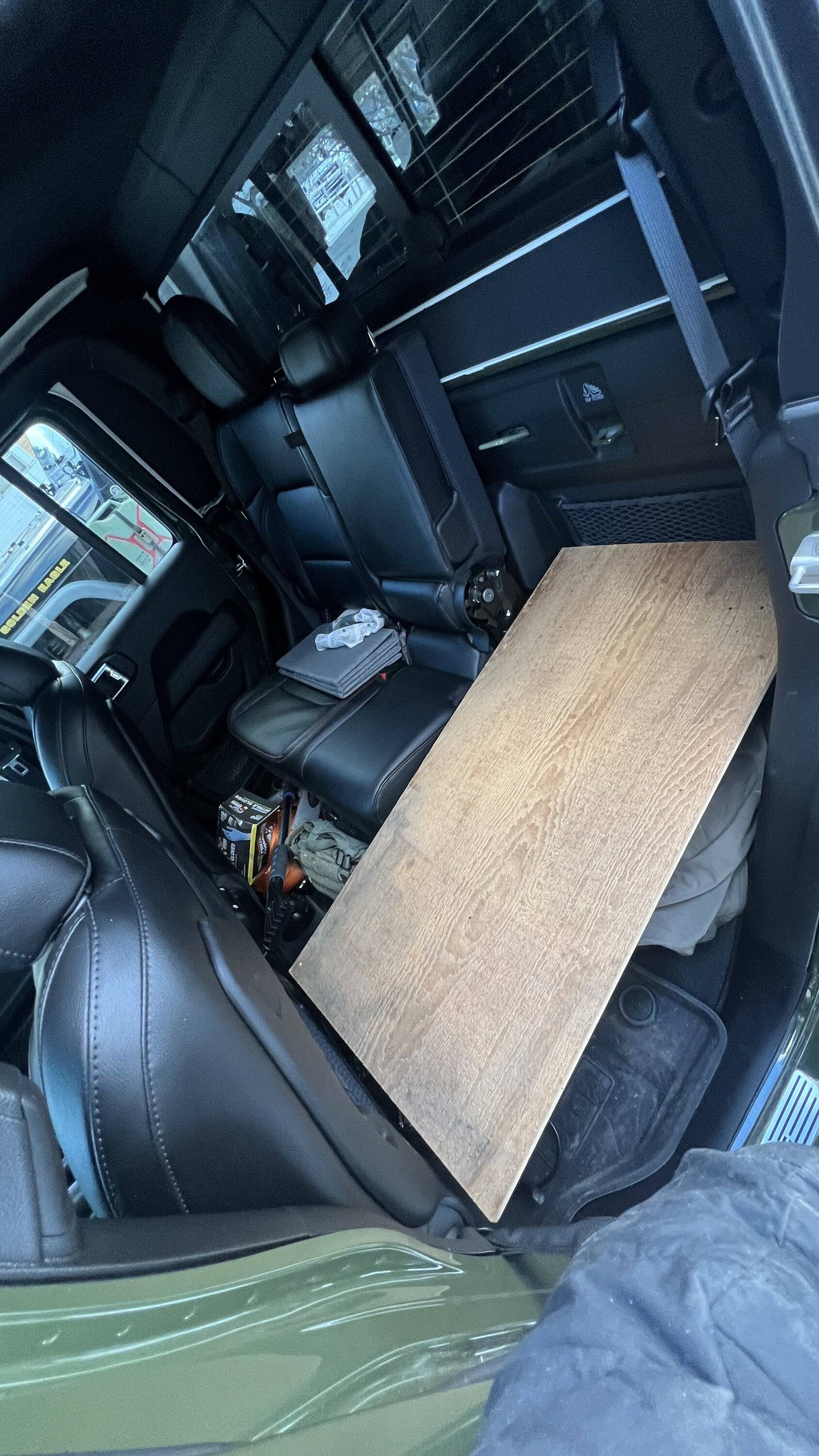
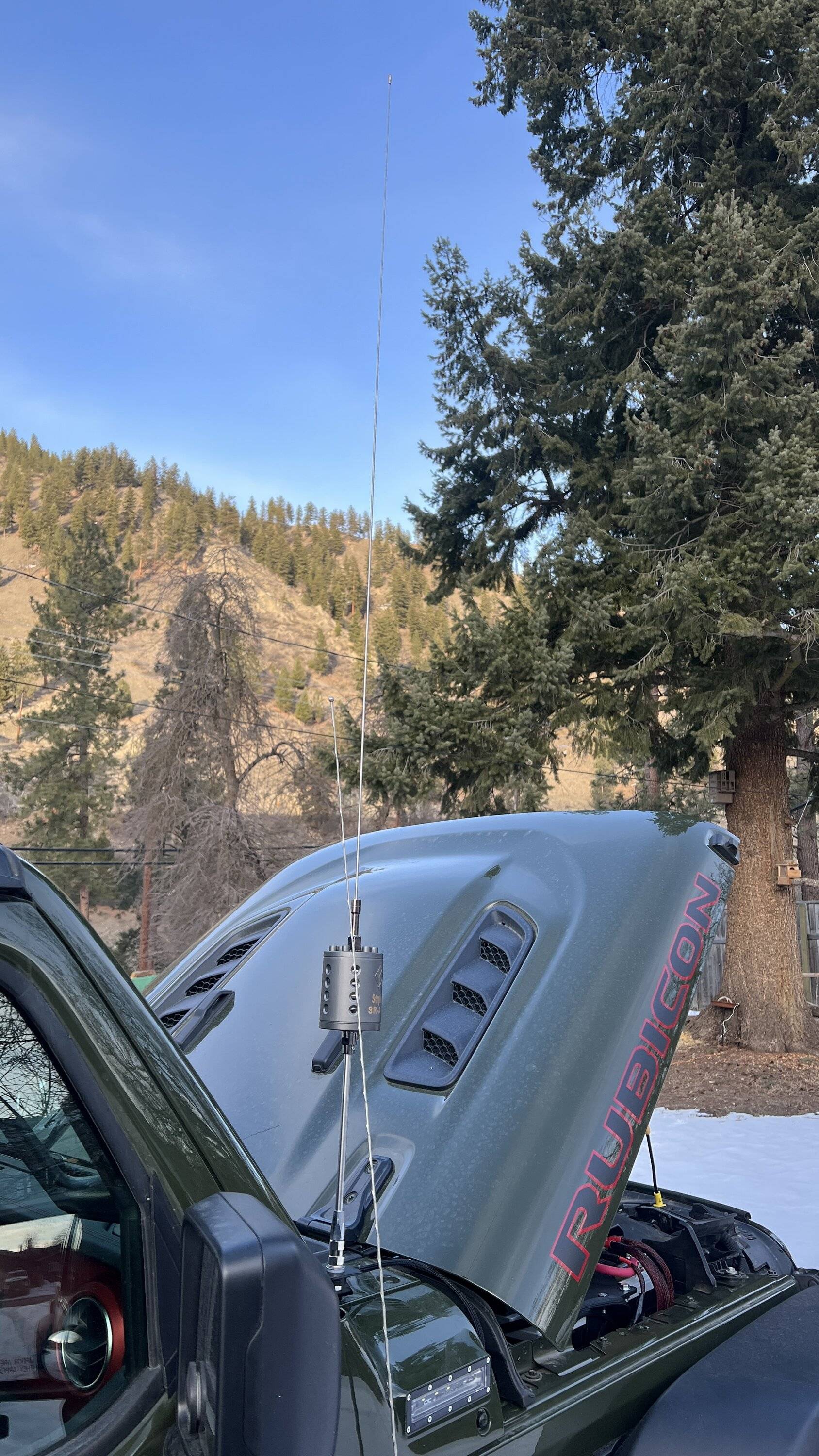
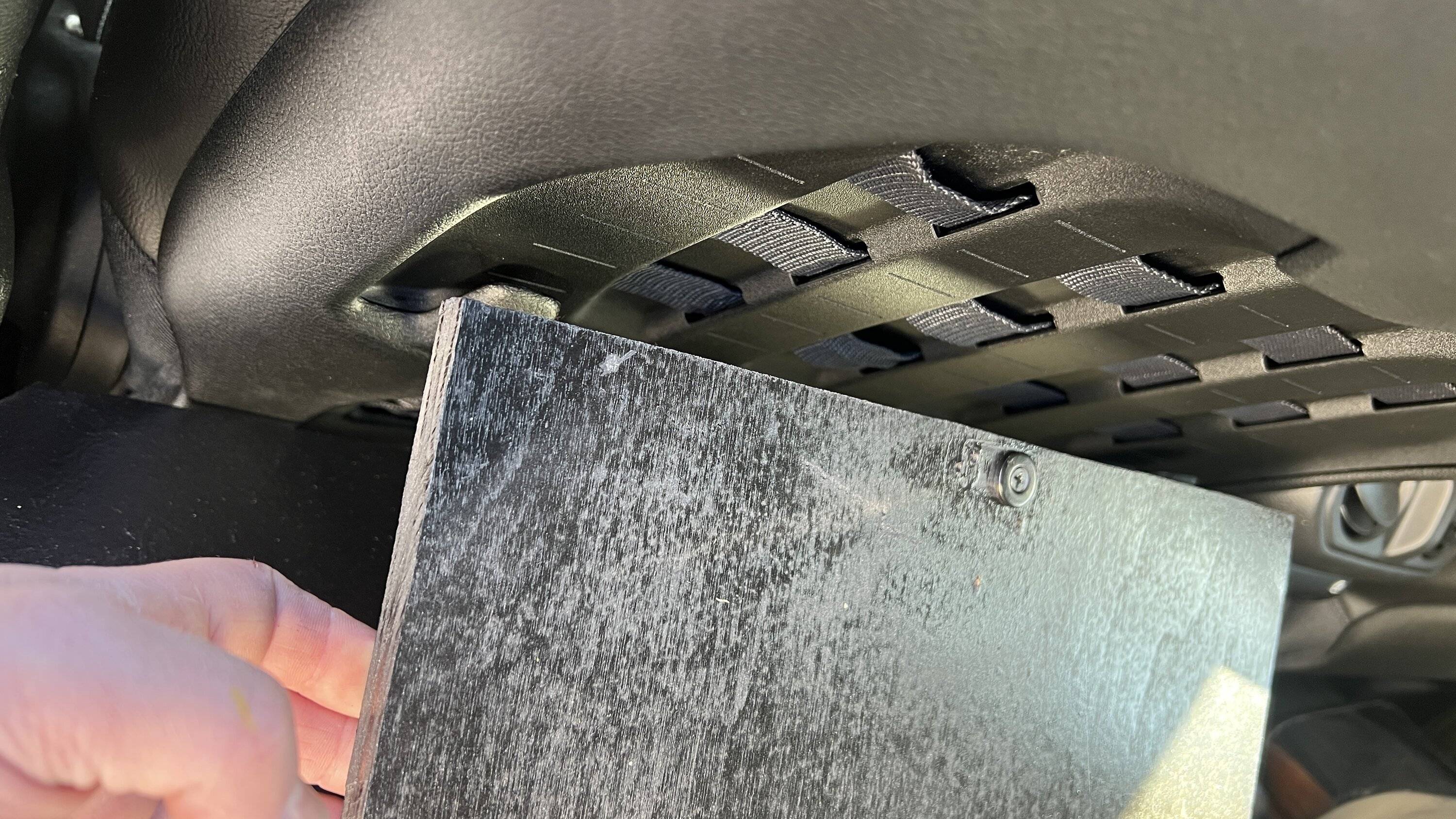
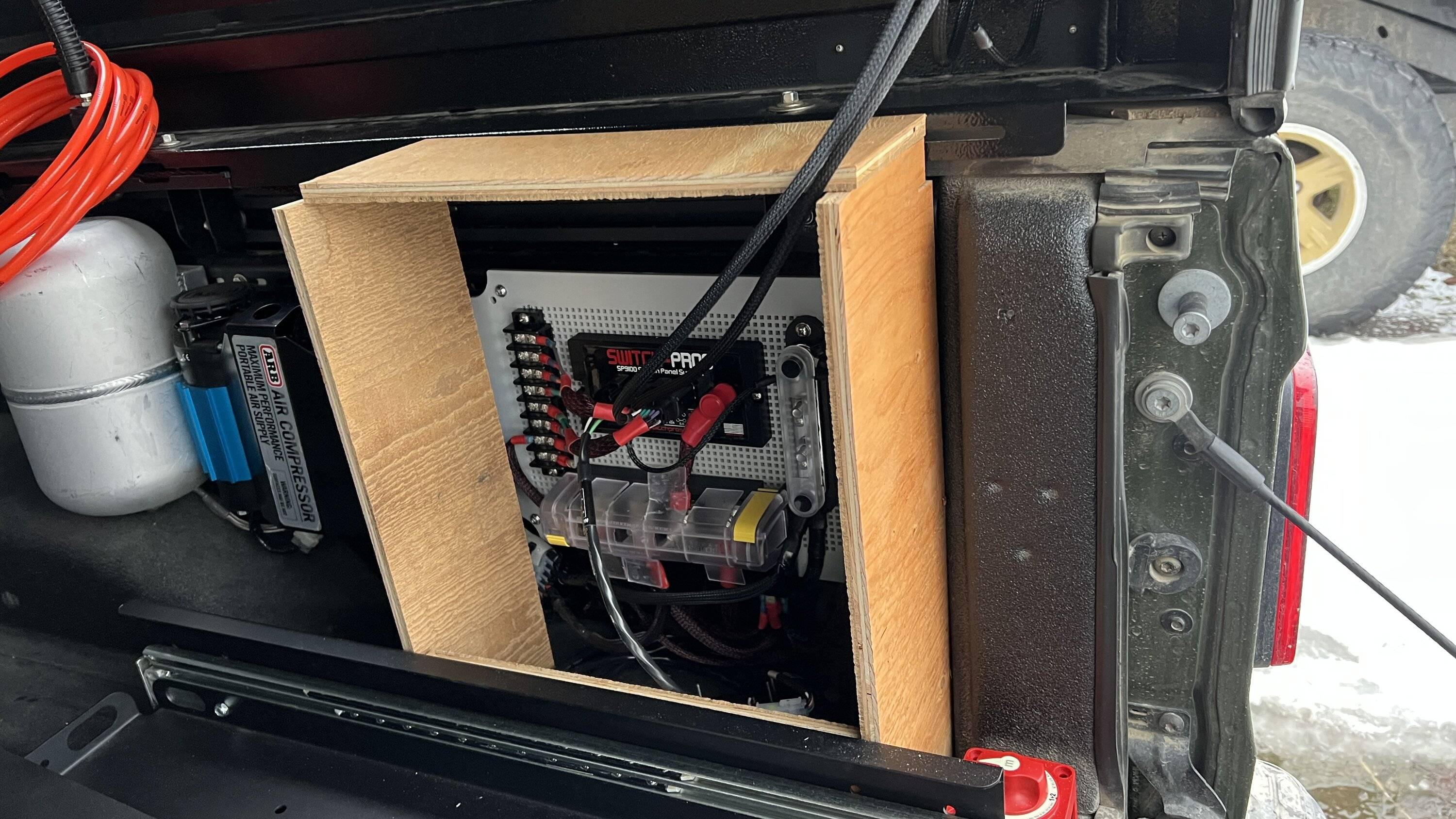
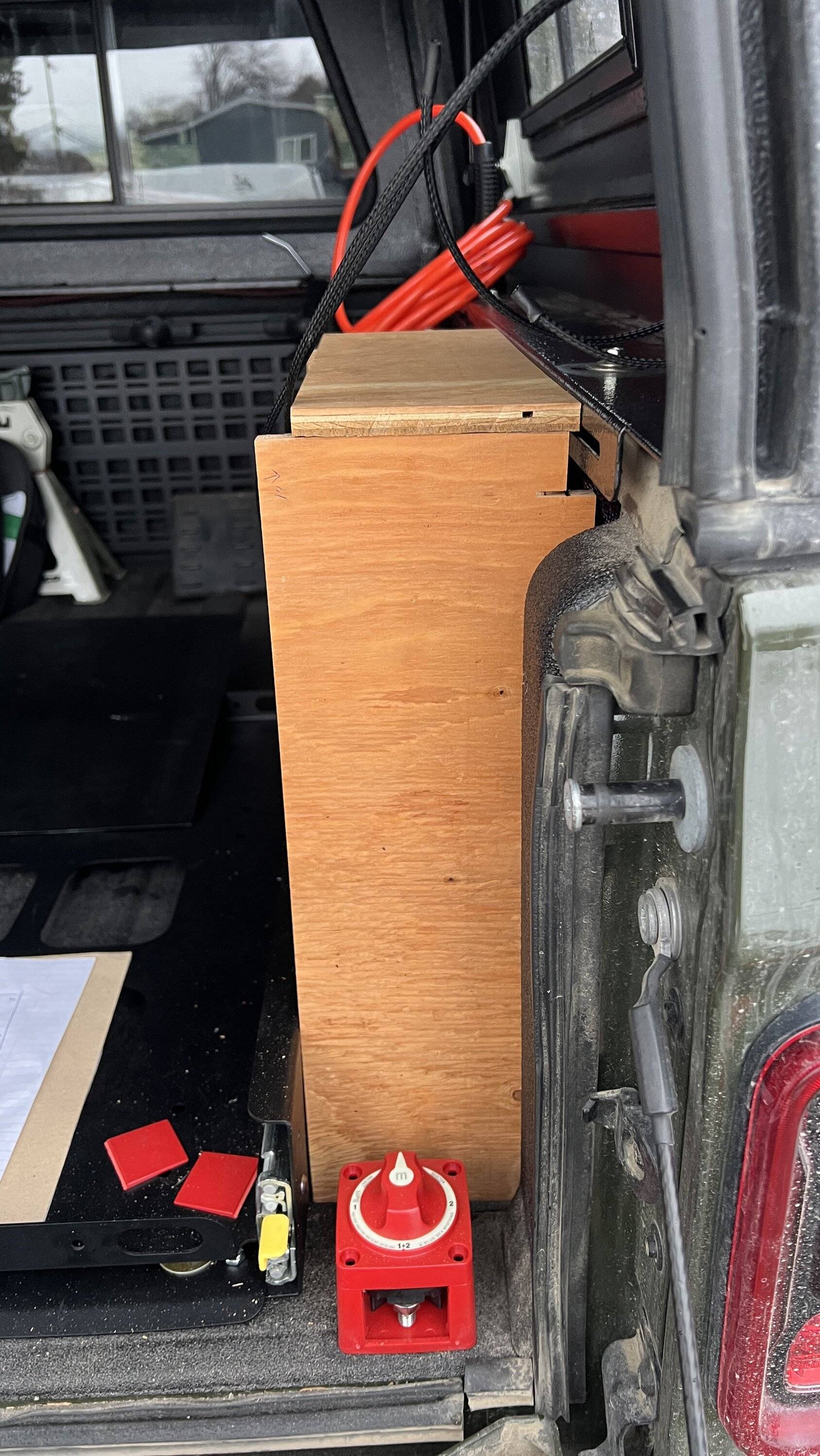
Today the G-Screen went on. As with most things it took twice as long as planned even though I planned for twice as long as expected - so I suppose that makes 4 times as long as expected.
Anyway - the most difficult part is the part I did not take pics of as it was getting dark out. Cutting parts of plastic trim.
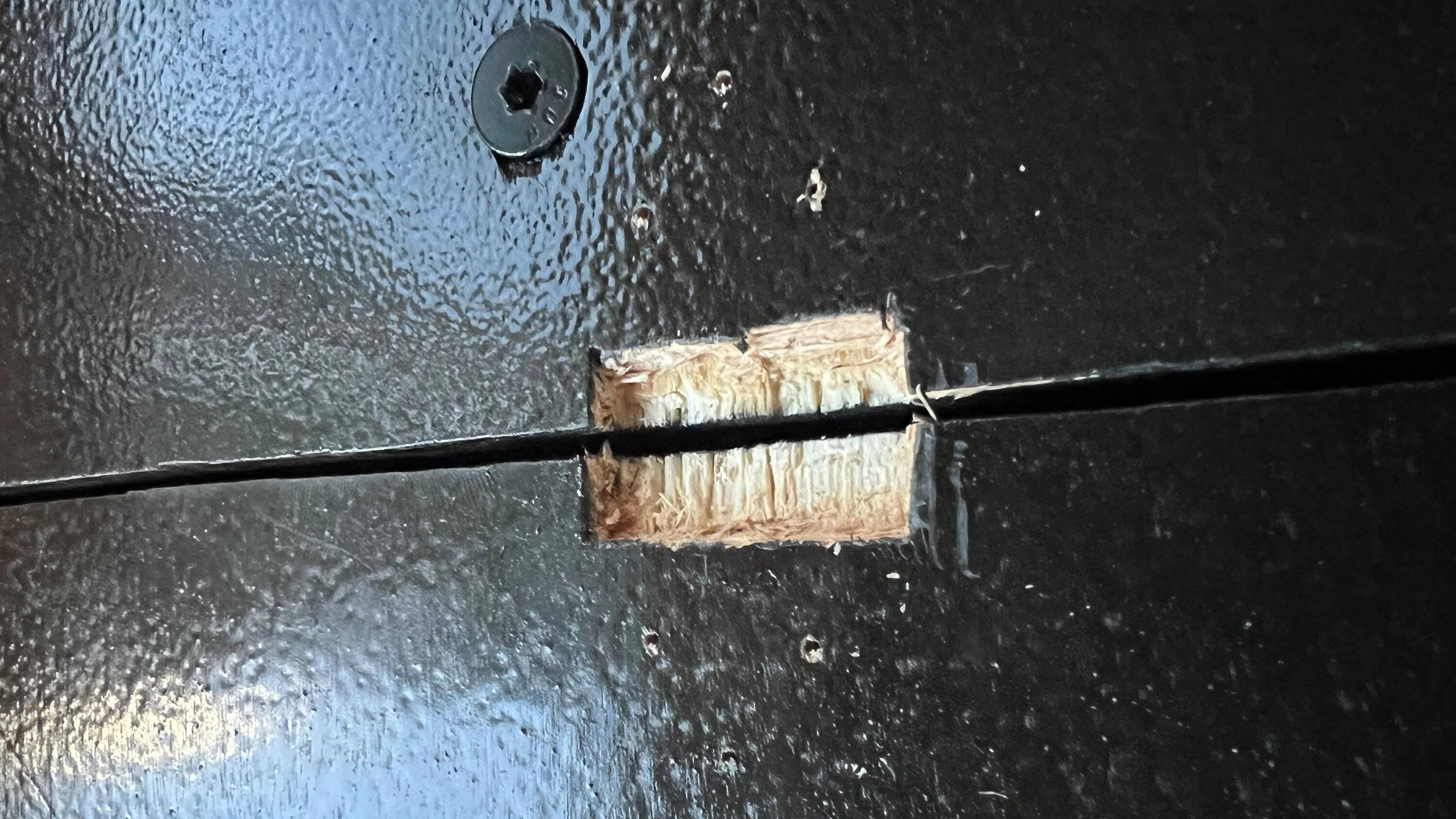
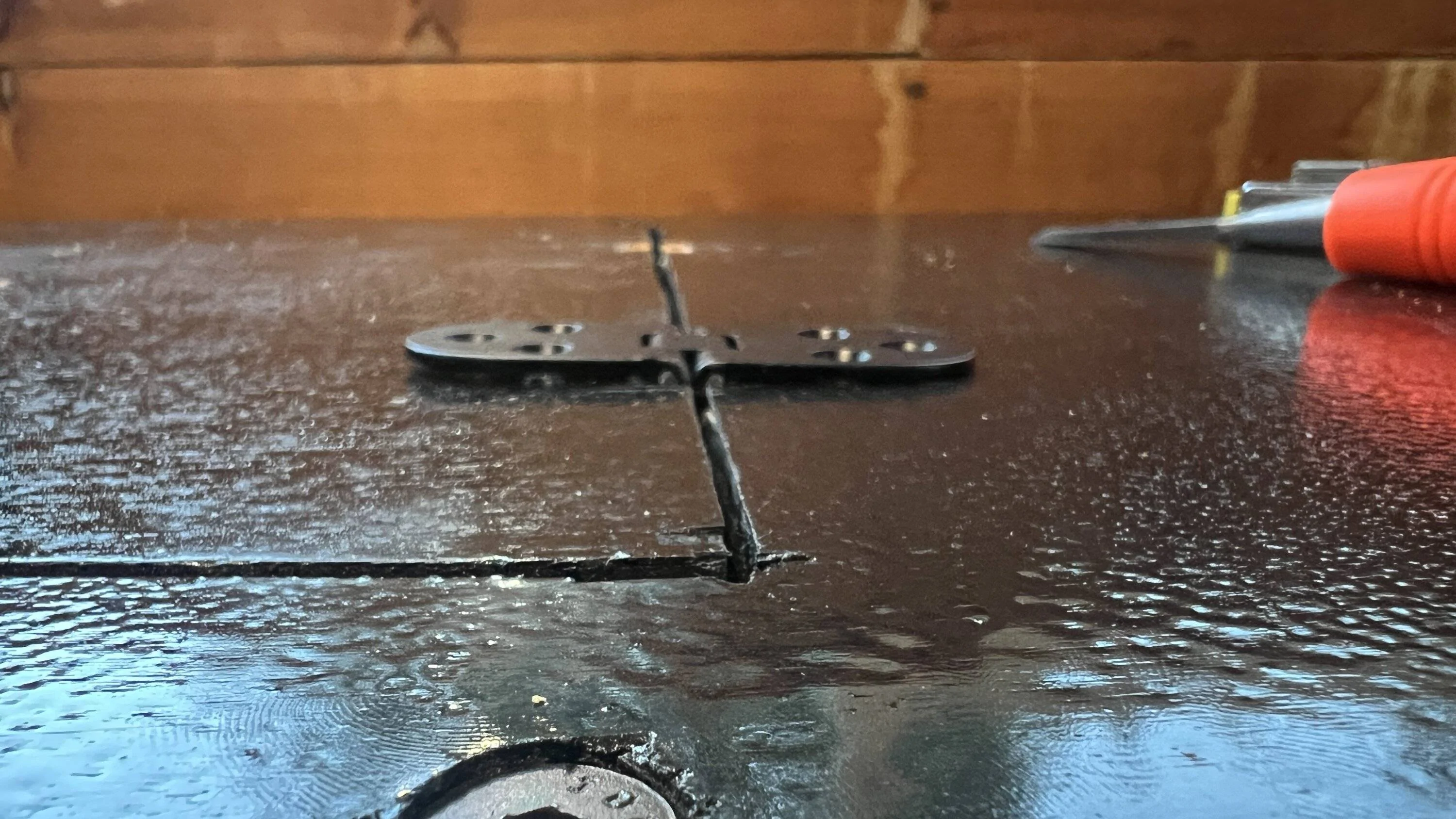
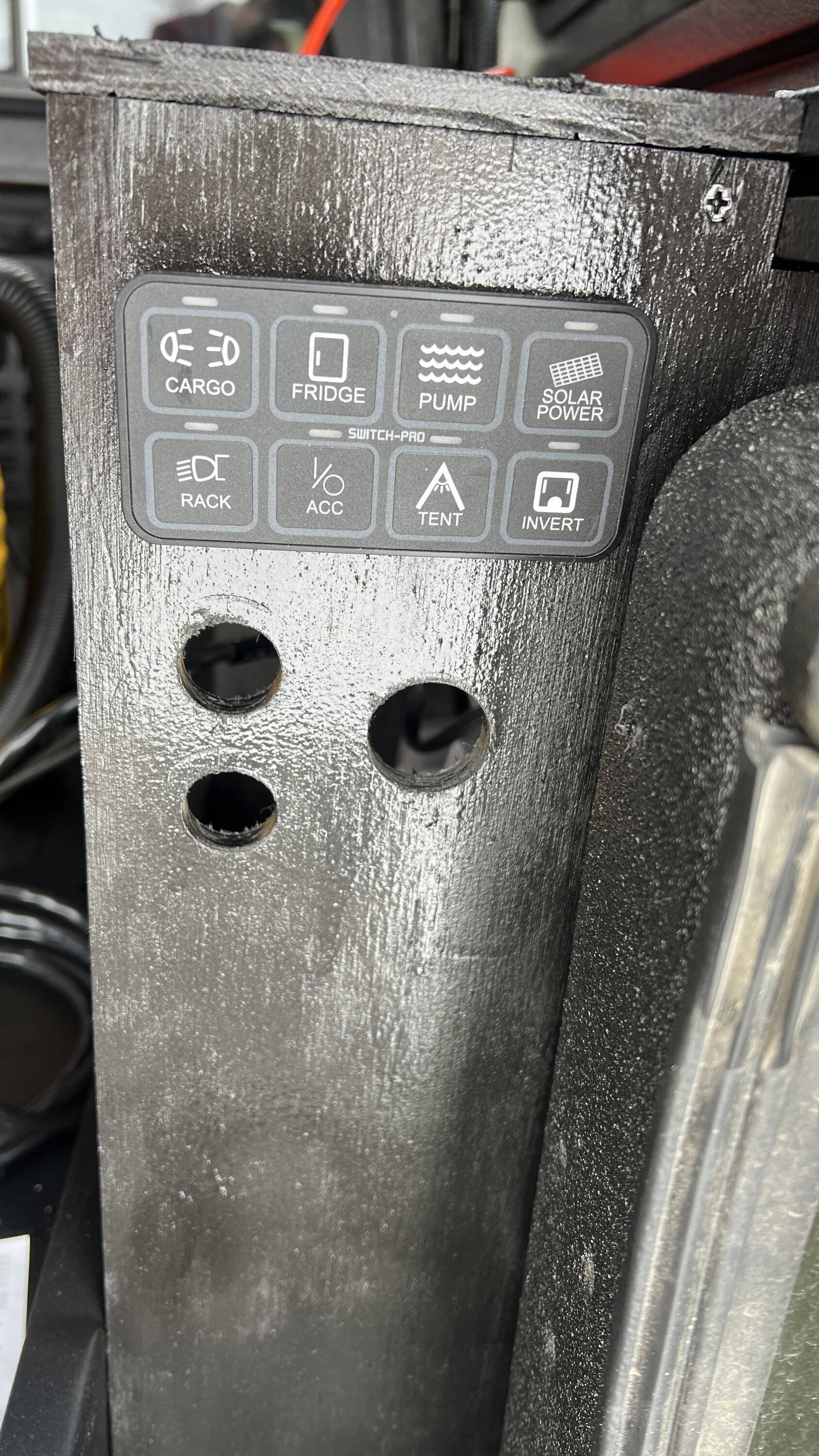
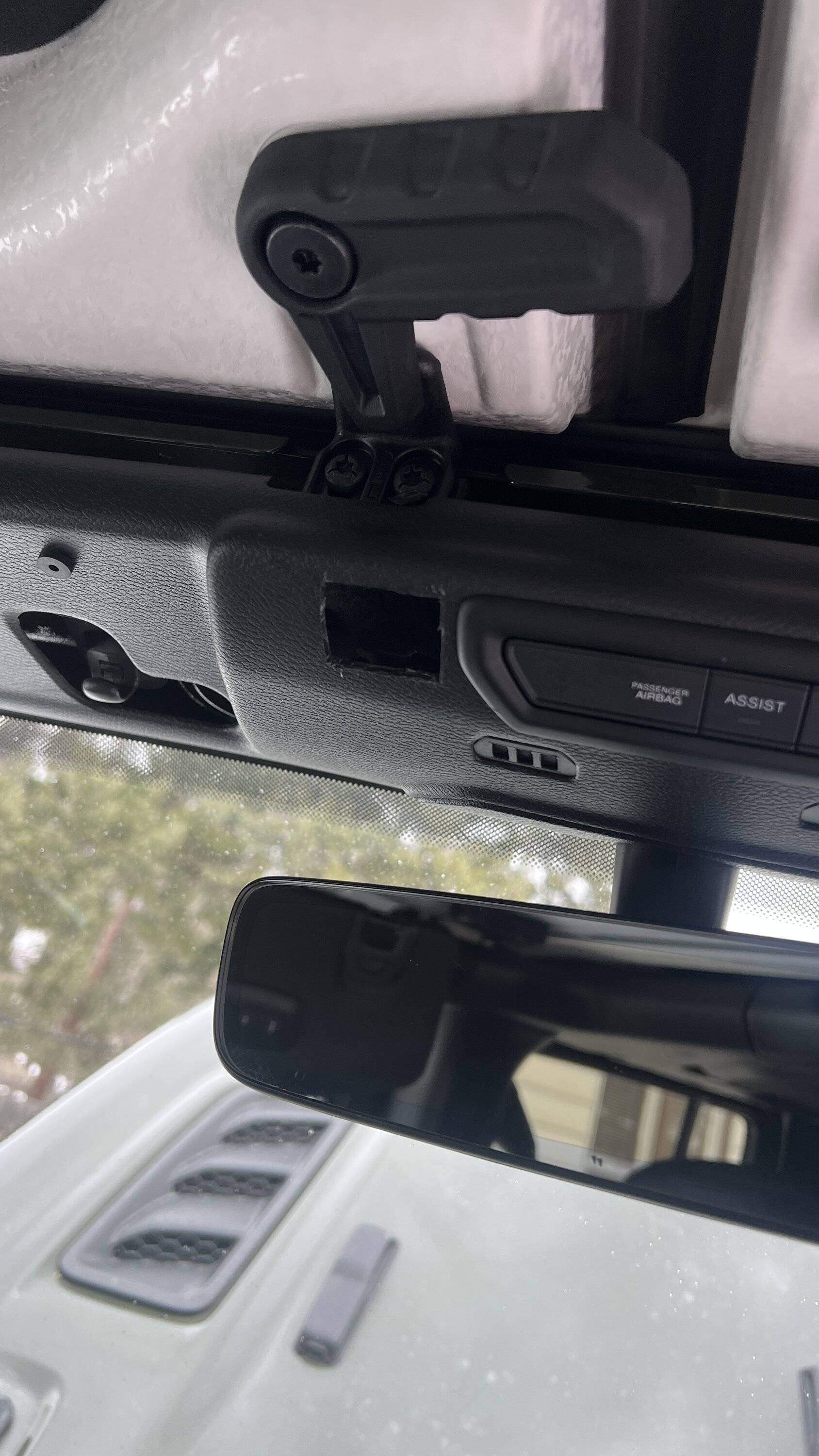
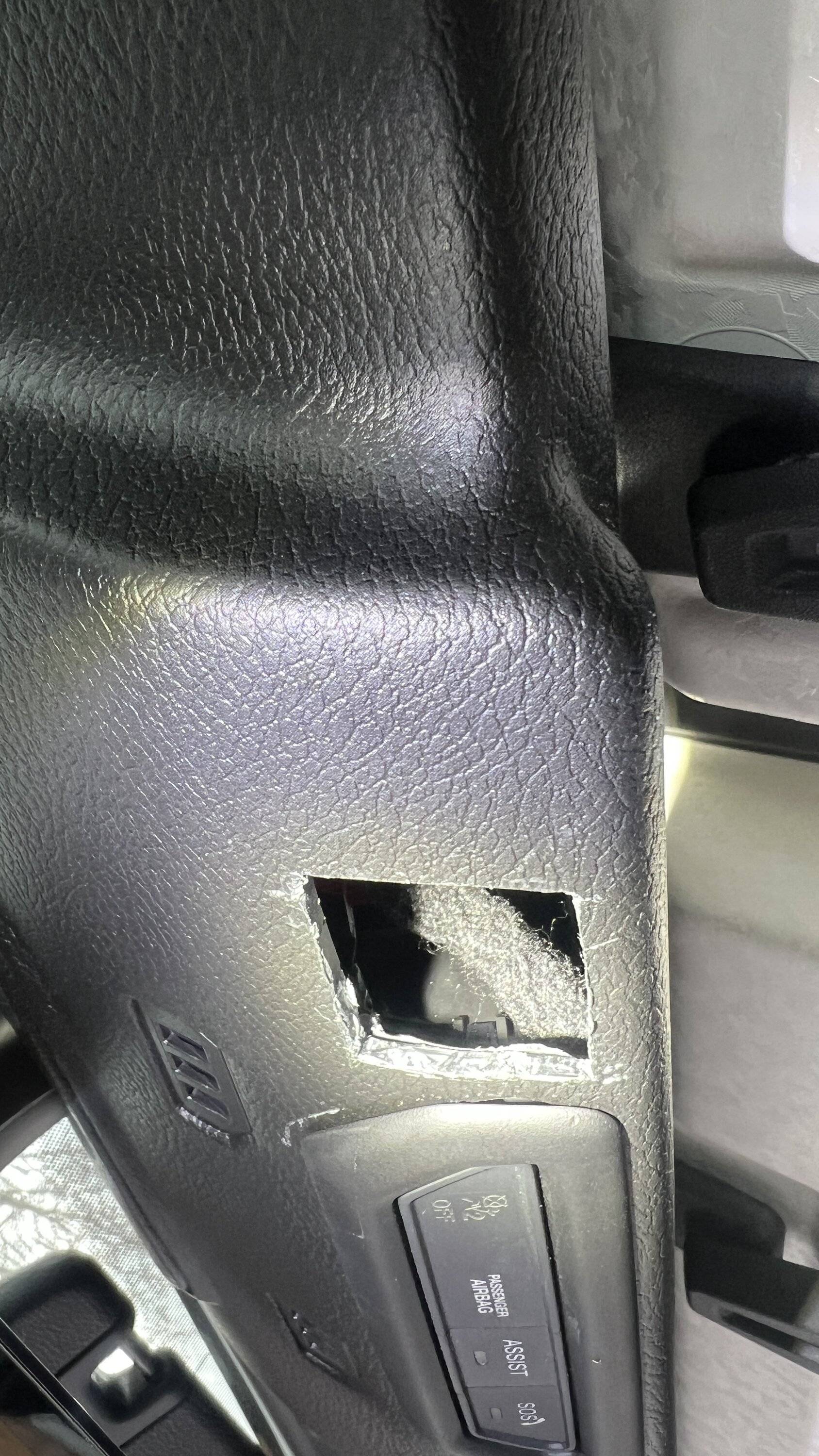
I chose to install the G-Screen in the same location as the Genesis video. Mostly because it really offers, I think, the best viewable location. And it's out of the way. The dash is cluttered enough and there really isn't a very good location there. So, preparations were made and I scored the portion that needed to be removed - reluctantly. I suppose a patch could be made later if needed. This part took quite some time. Probably an hour to be exact. I used multiple scores with a razor blade over and over again which was time consuming and slow due to taking caution to not cause any deep gashes in visible areas. I could have used a little die grinder, but in past experiences, that often leaves plastic melted and not looking so great.

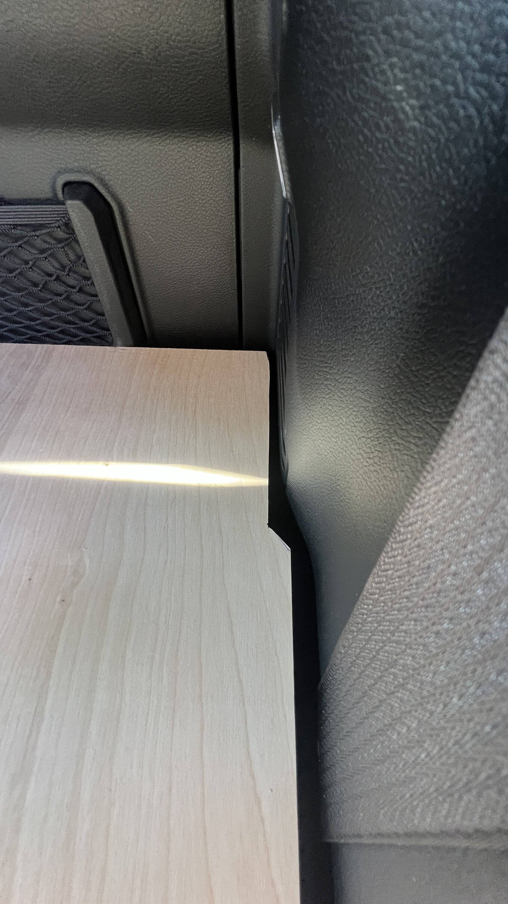
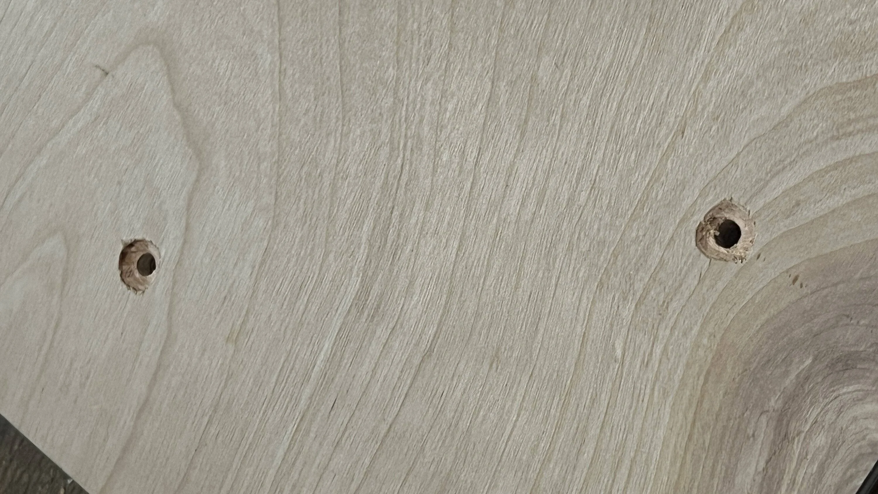
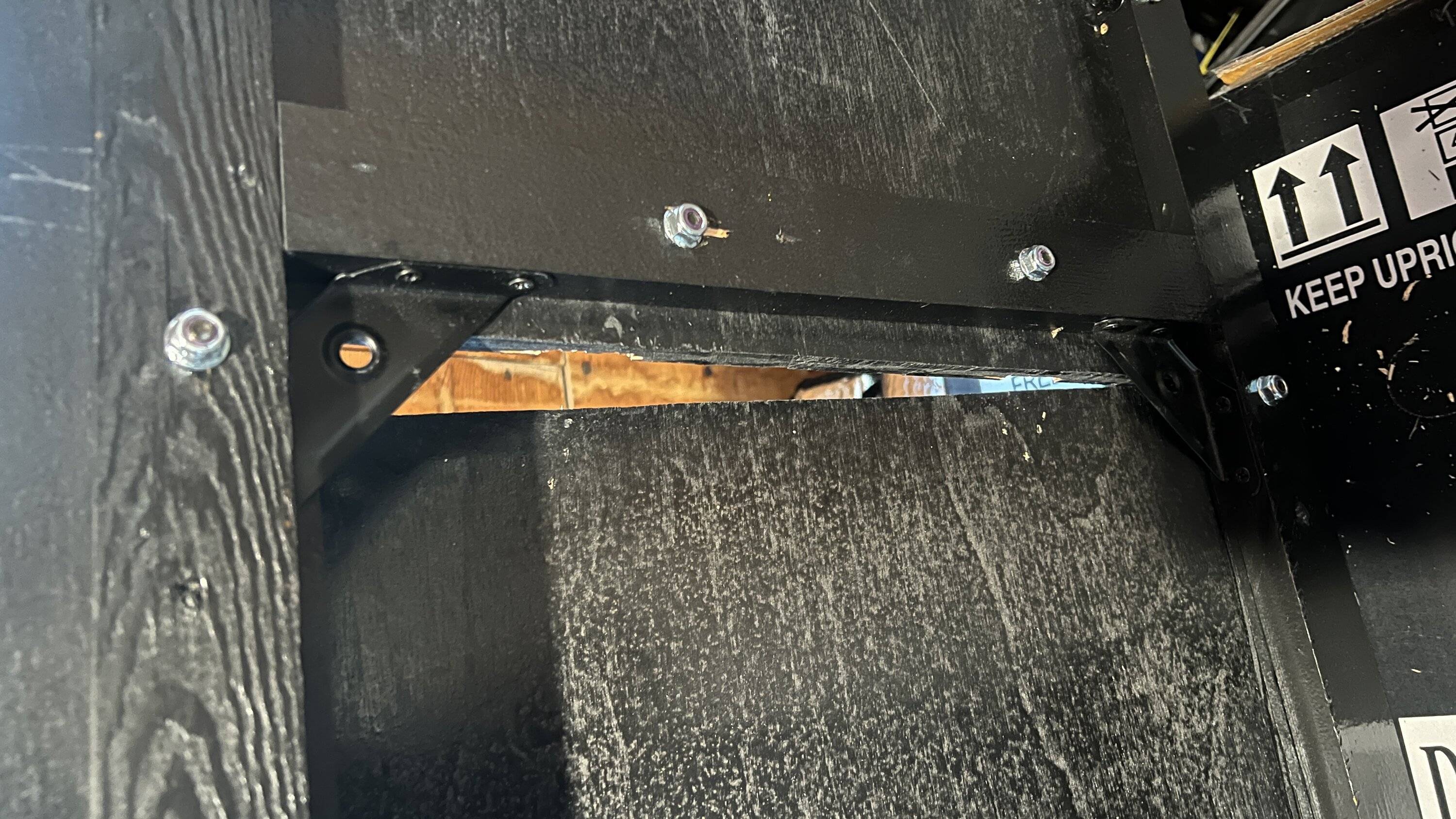
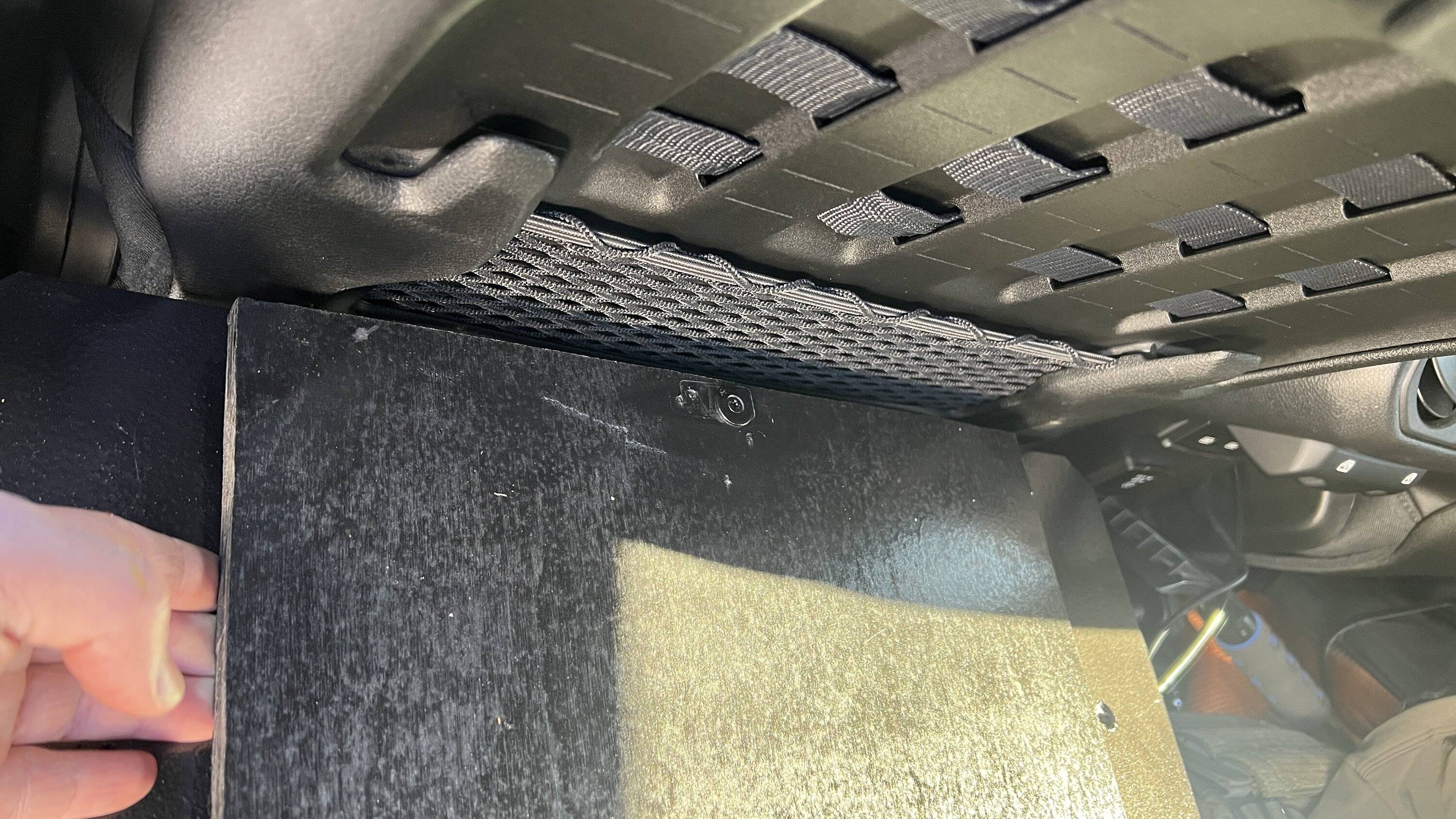
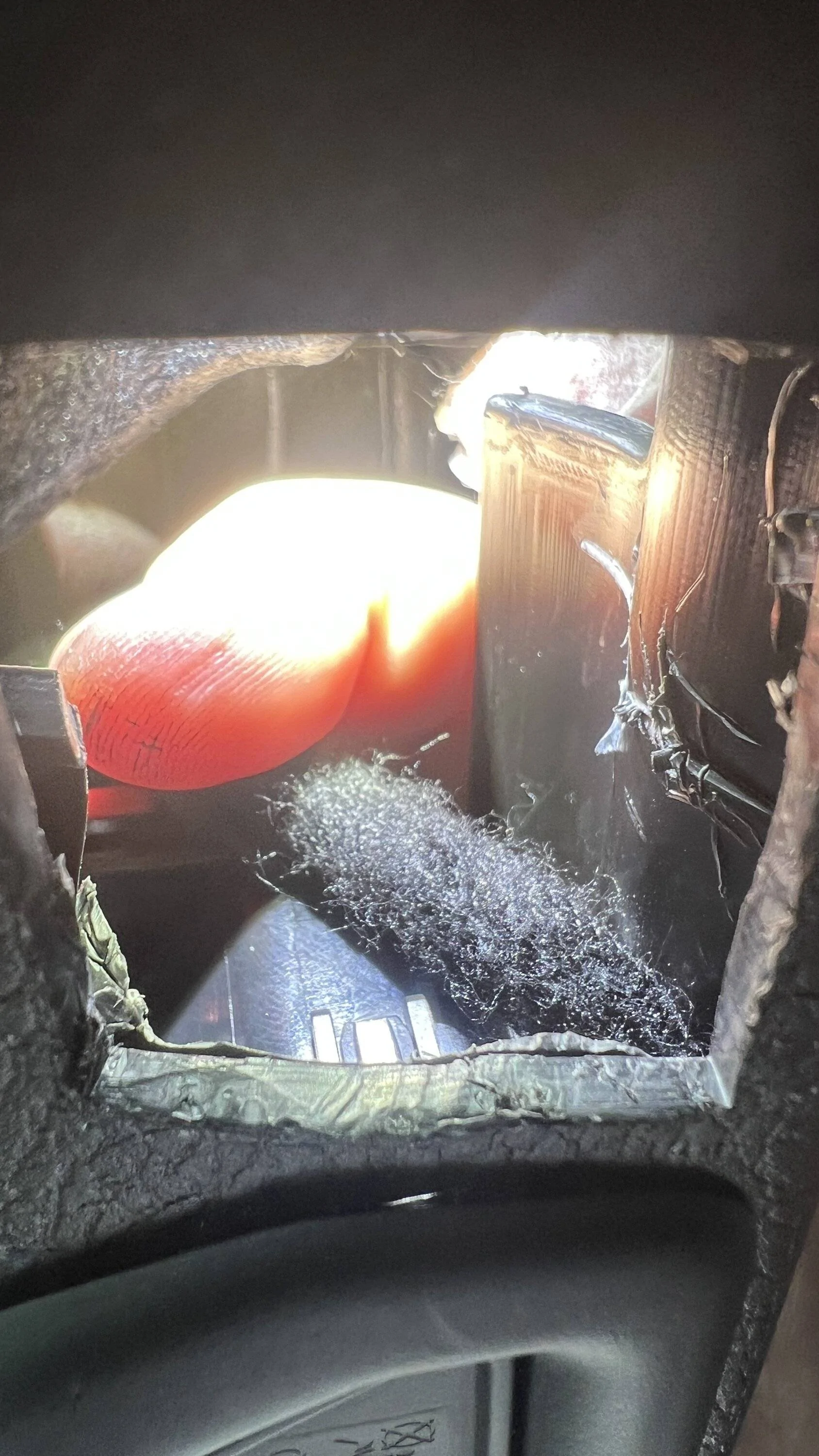
I did cut a little too far to the passenger side, making it a tight squeeze for the wiring harness. As you can see, there are also wires there that I didn't realize were so close - thankfully I didn't knick any of them!
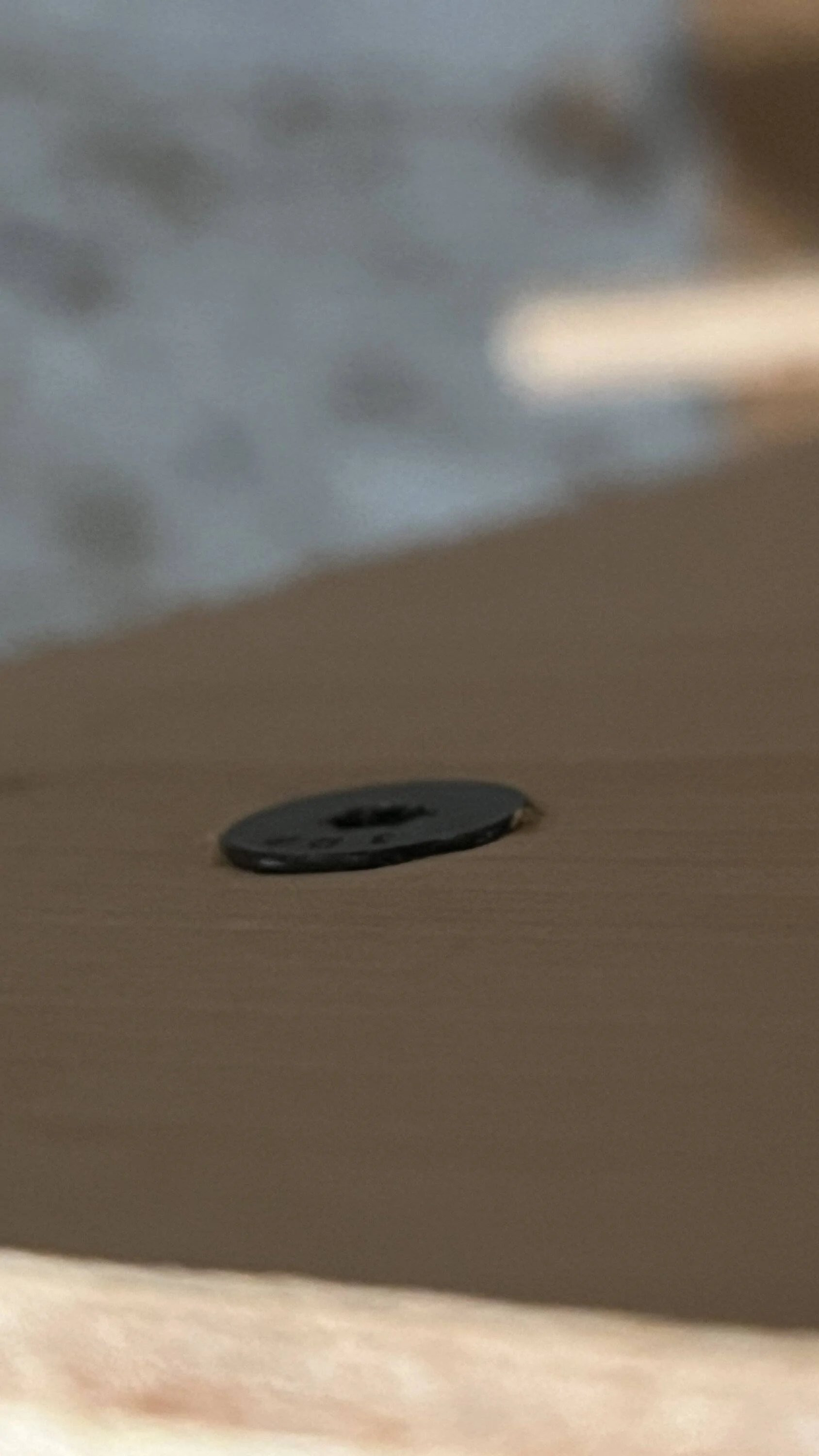
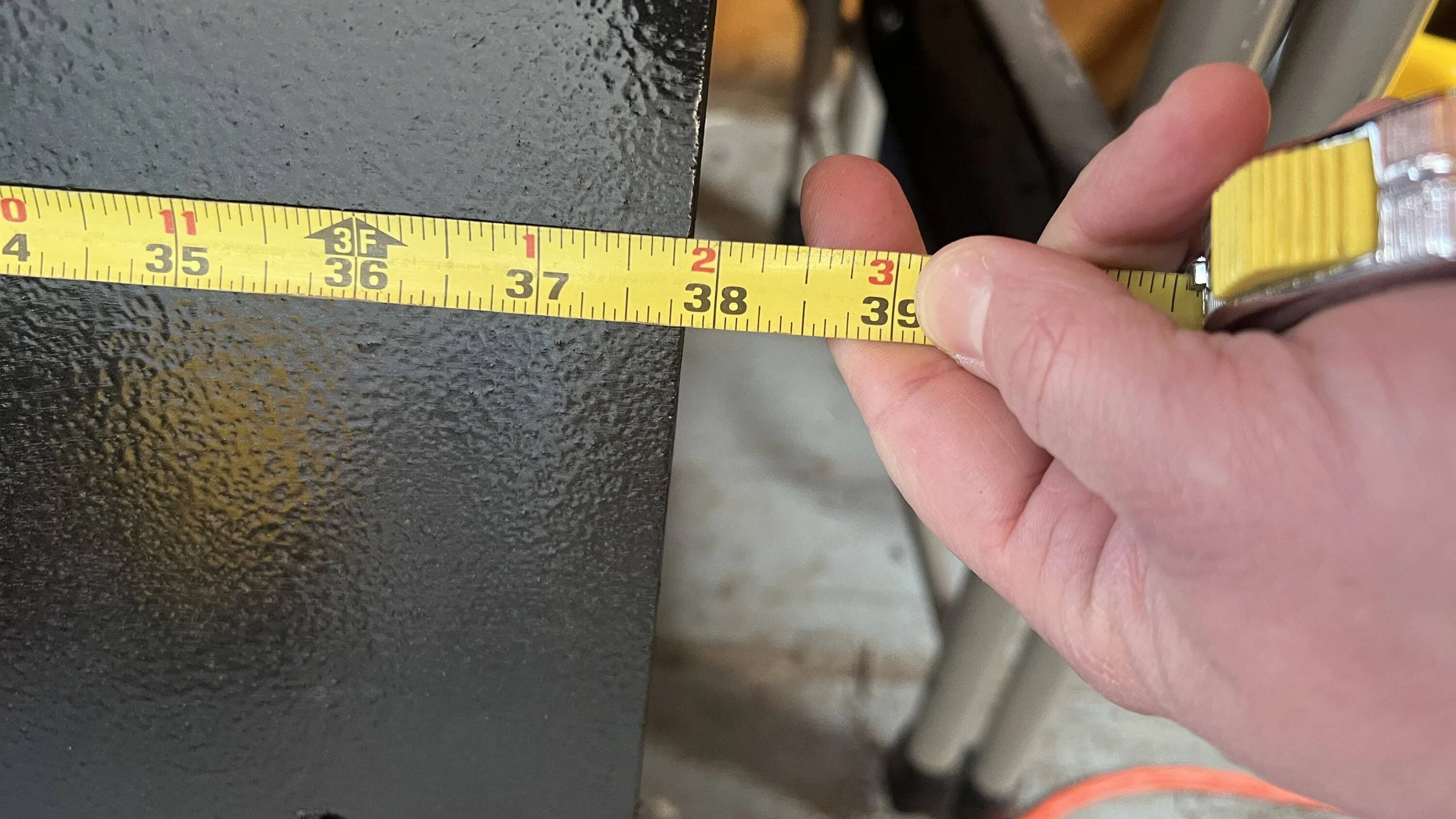
Obviously I did make a couple of oopses....but from a normal sitting position, you have to be OCD like me to really know its there. The most challenging part I failed to get pics of. Finding a place to put the control box. It's not very big. Maybe 1.5" by 2.5" by 0.75". But there is hardly any space up there as it is. I had to, reluctant cringe, cut more.... There just wasn't a long enough ribbon wire to put the control box further off to the side. So it is basically right behind the SOS button. Unfortunately, even with a bunch of plastic back there cut and out of the way, it still bows out. But since it is in the middle, it is not super obvious, and again, unless you have OCD like myself, the average person would likely have NO clue. But, I did have to cut 1 retaining clip, and a bunch of 'structural' plastic. I have some worries that it might rattle and make noise now - for which if it does I will have to open it back up and put some felt tape in place.
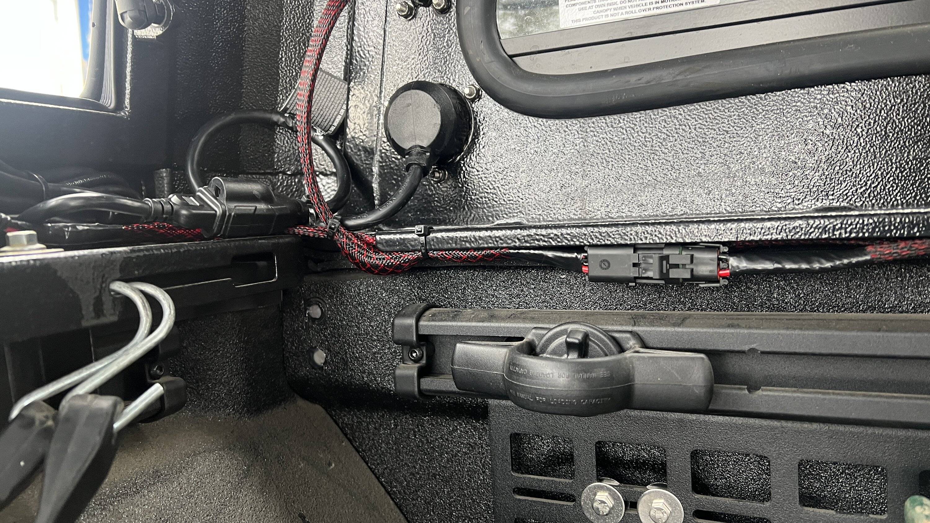
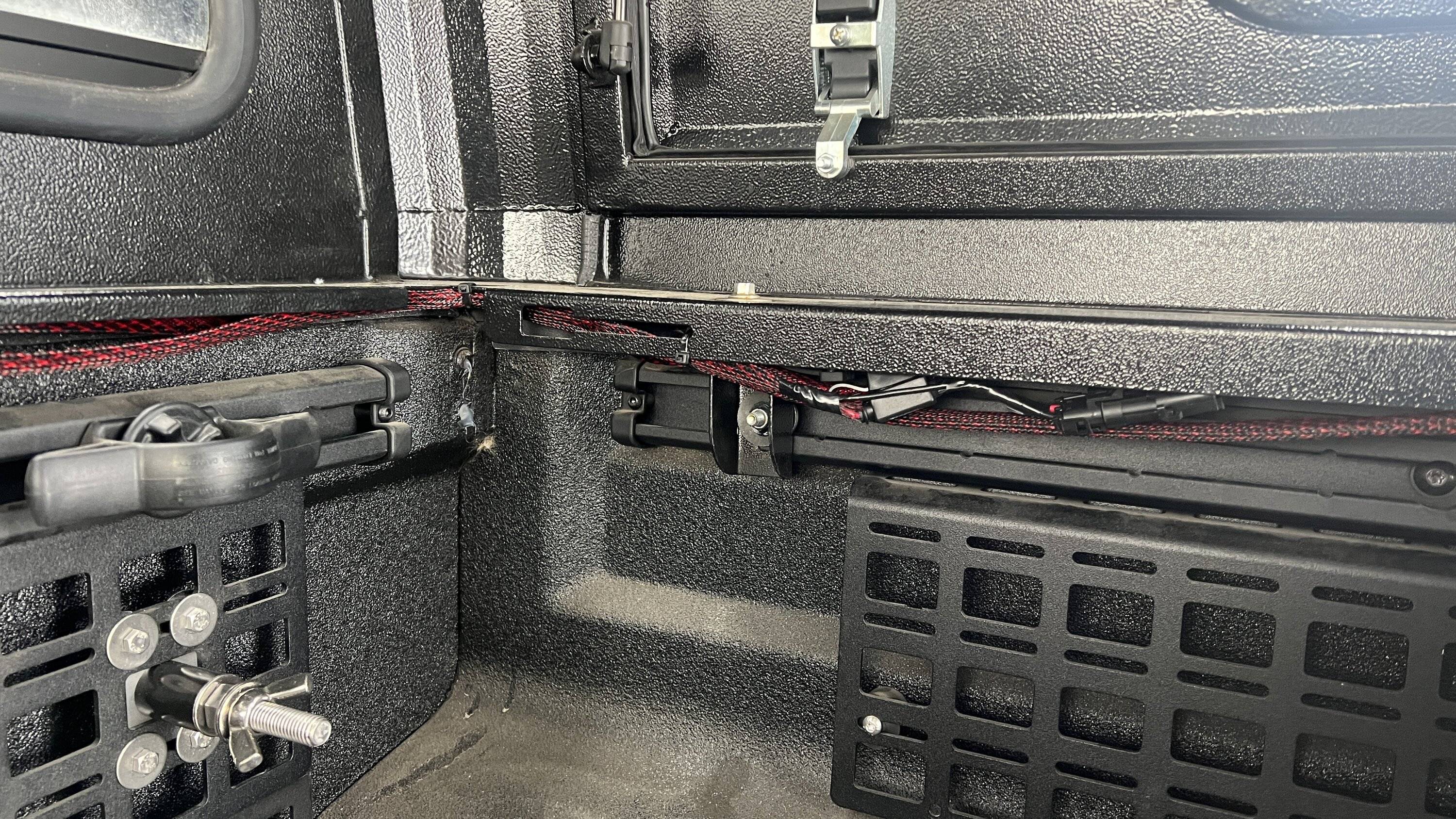
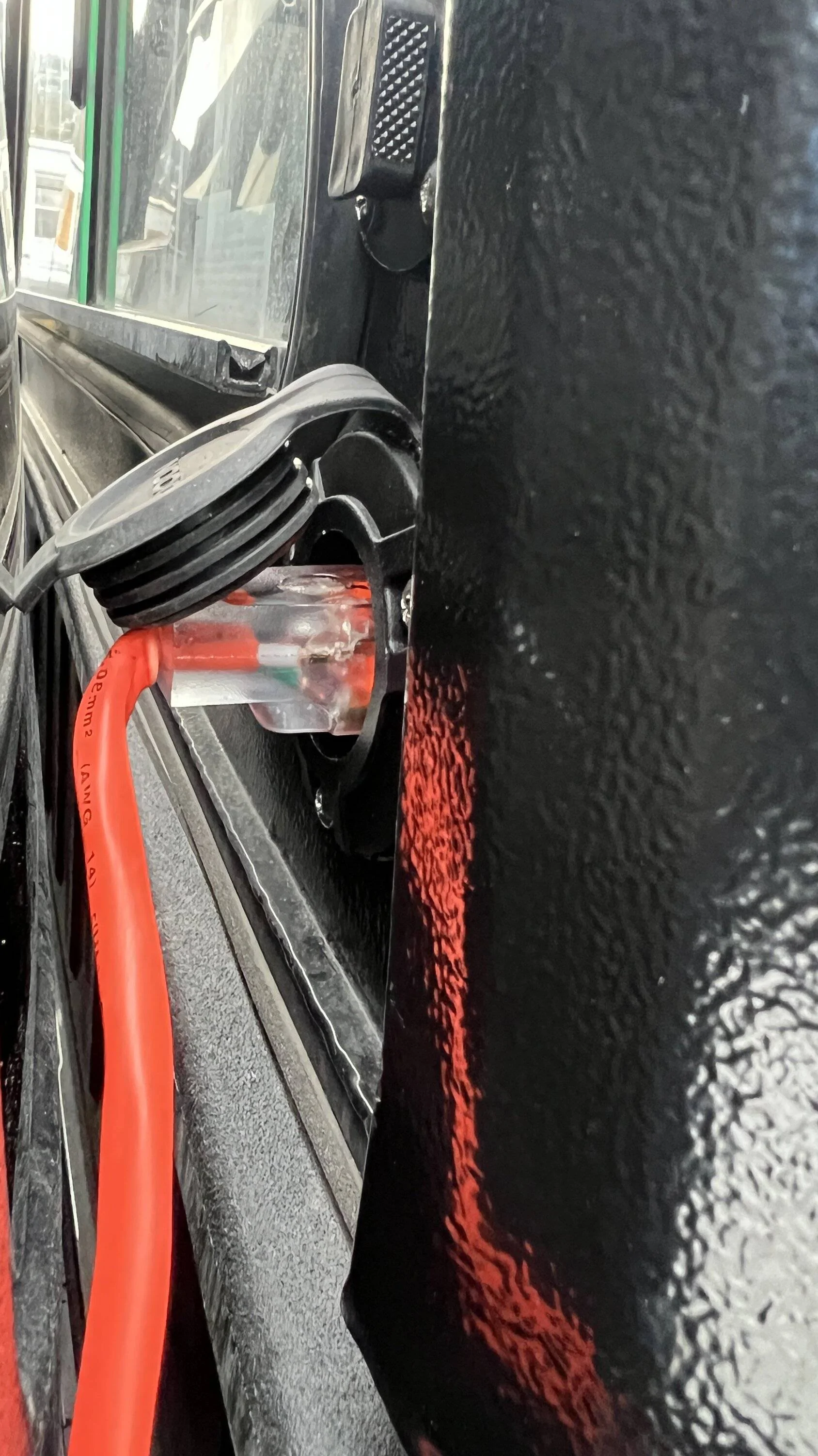
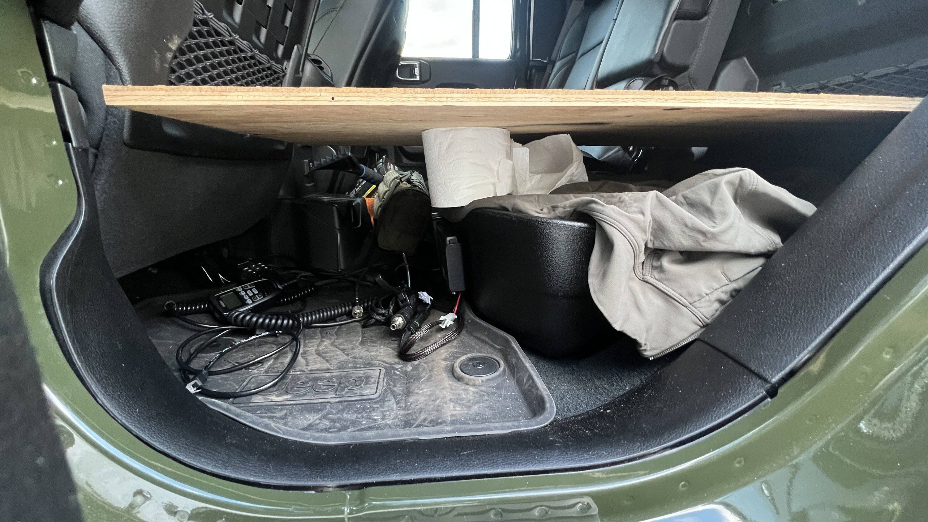
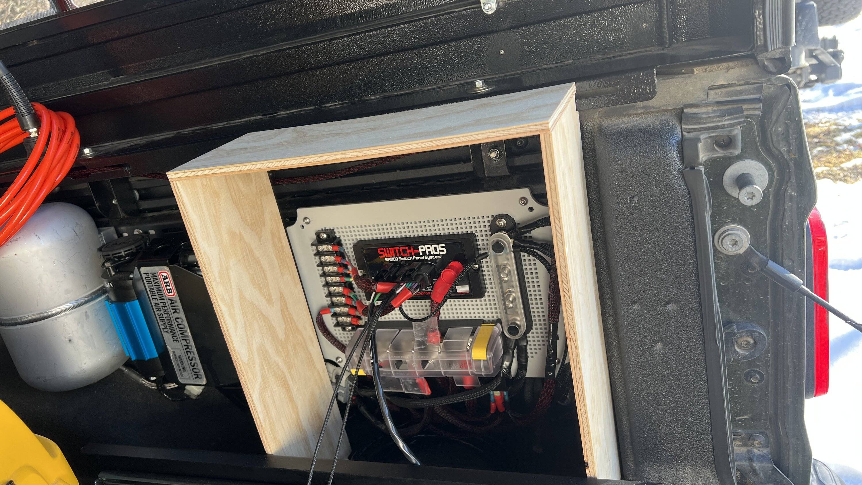
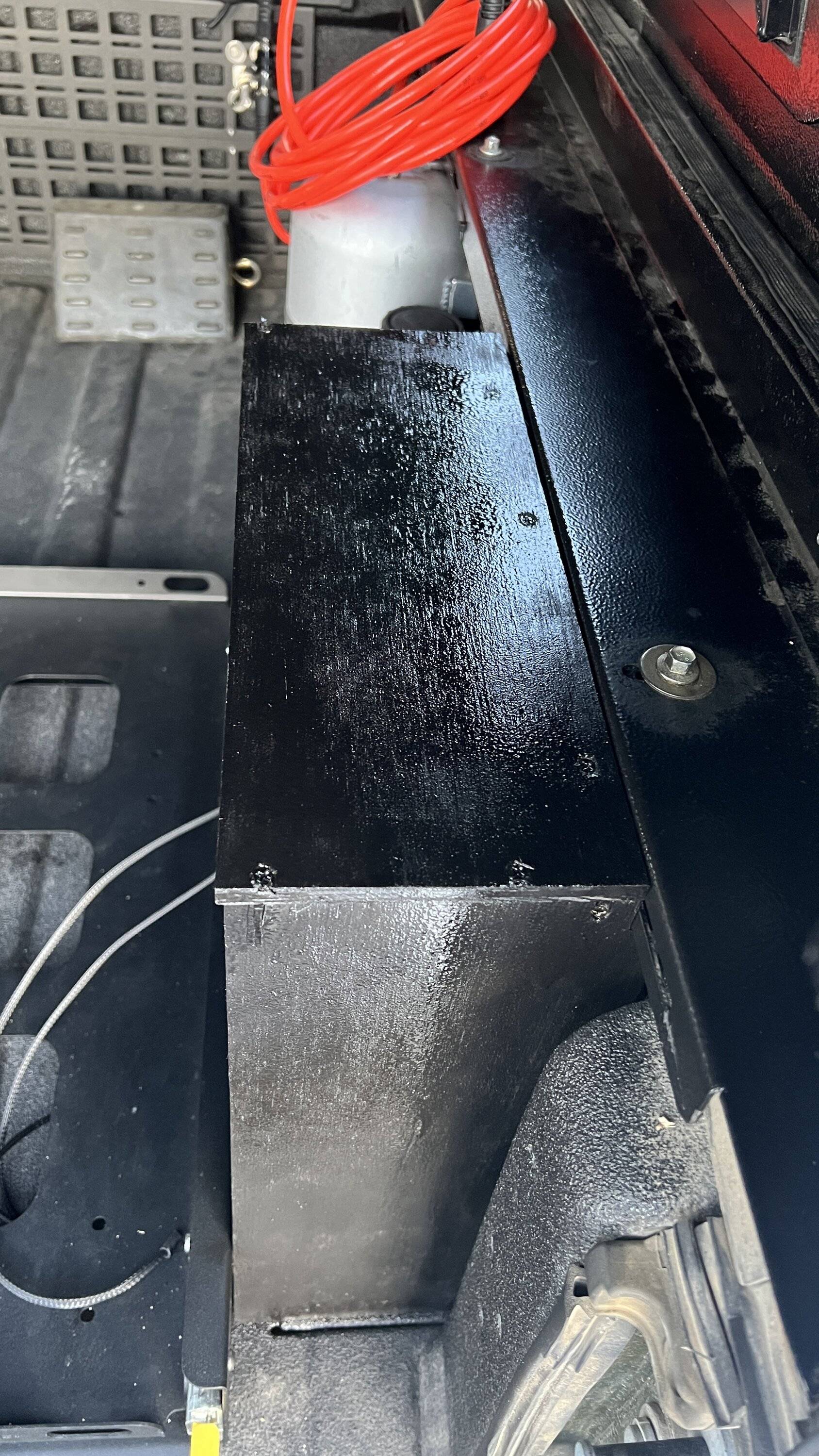
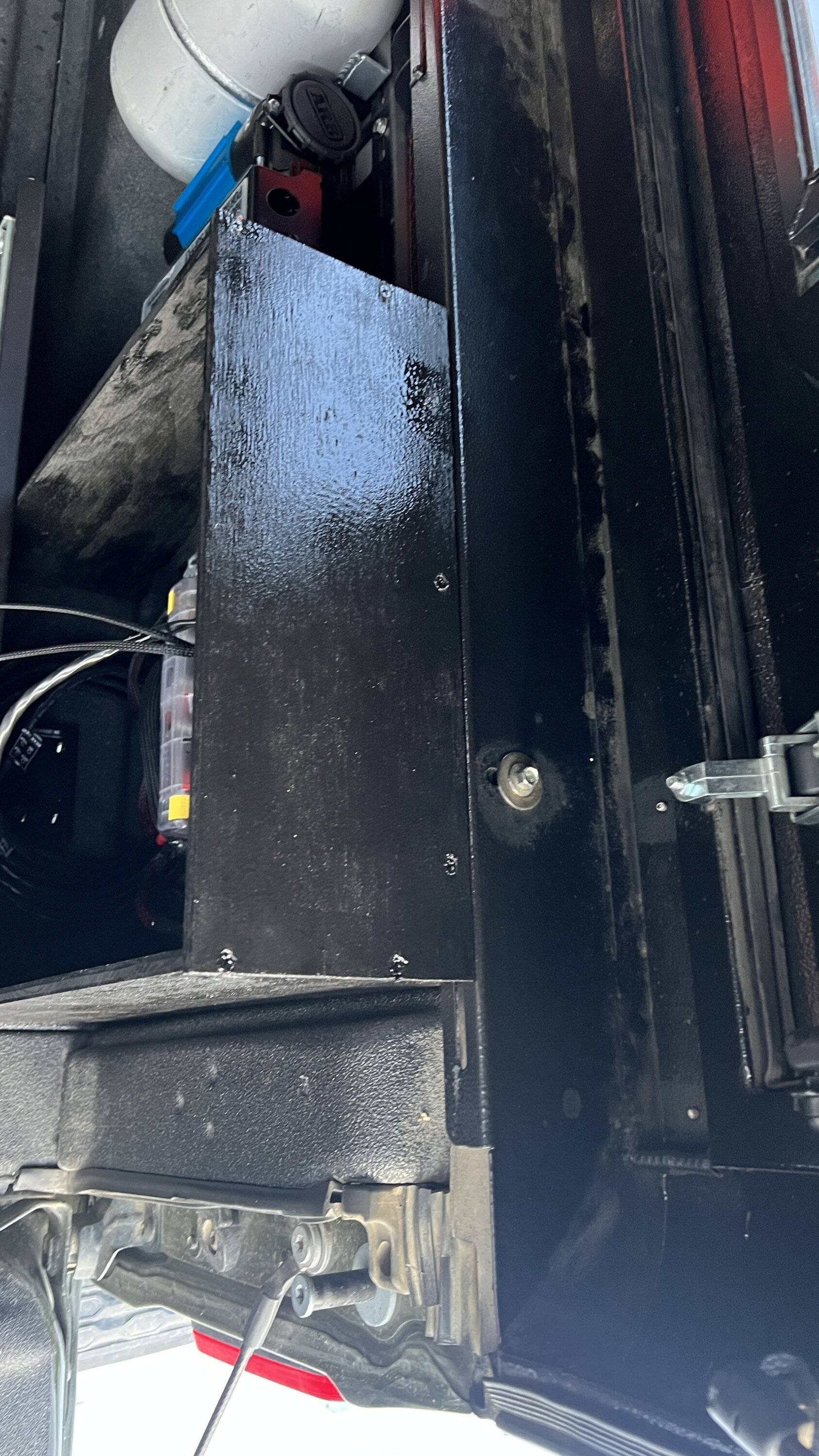
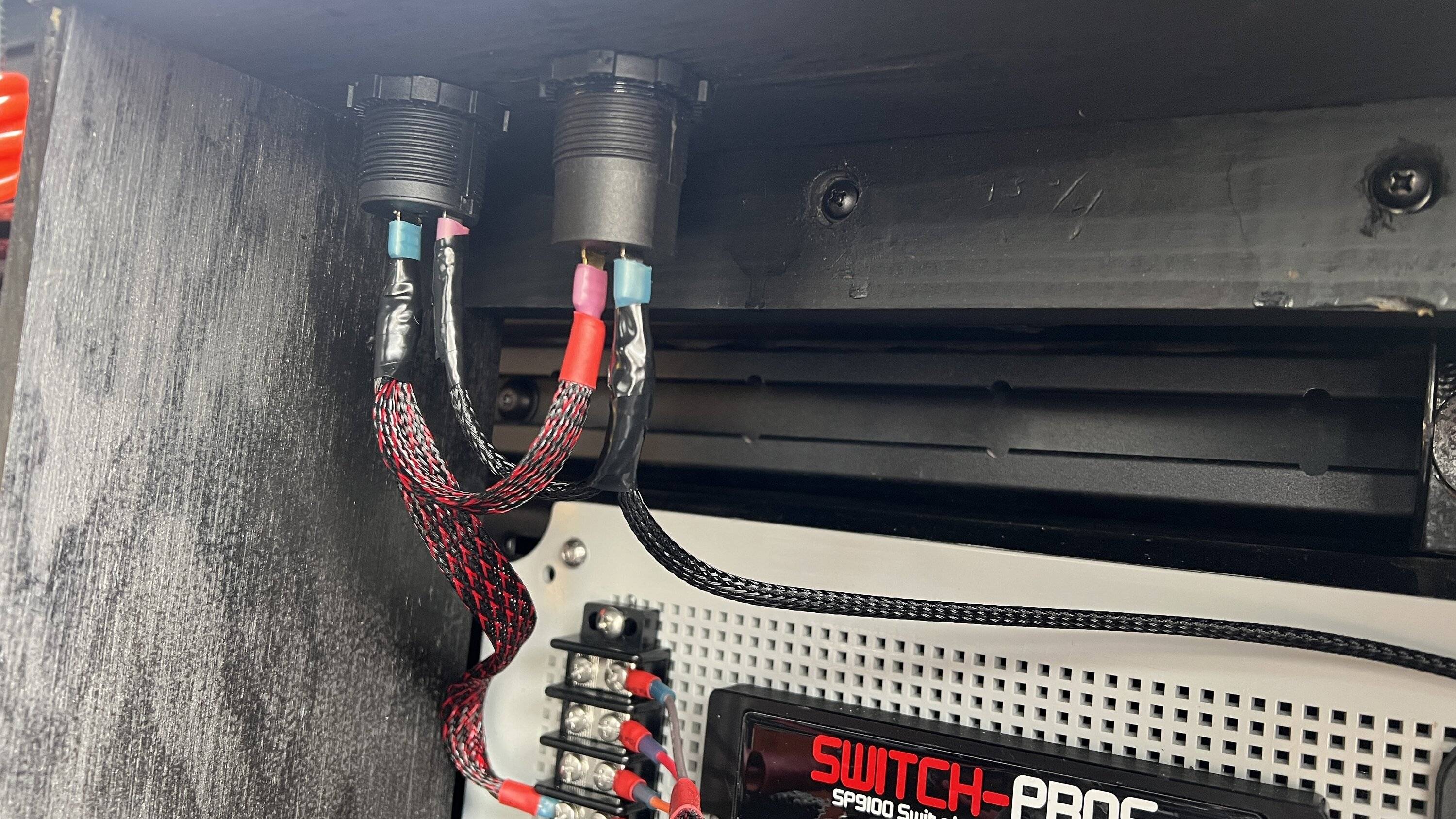
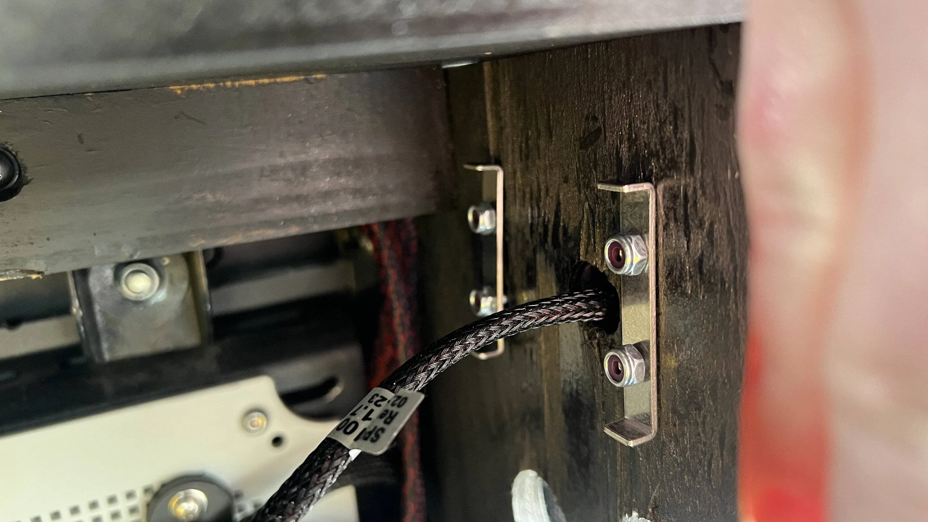
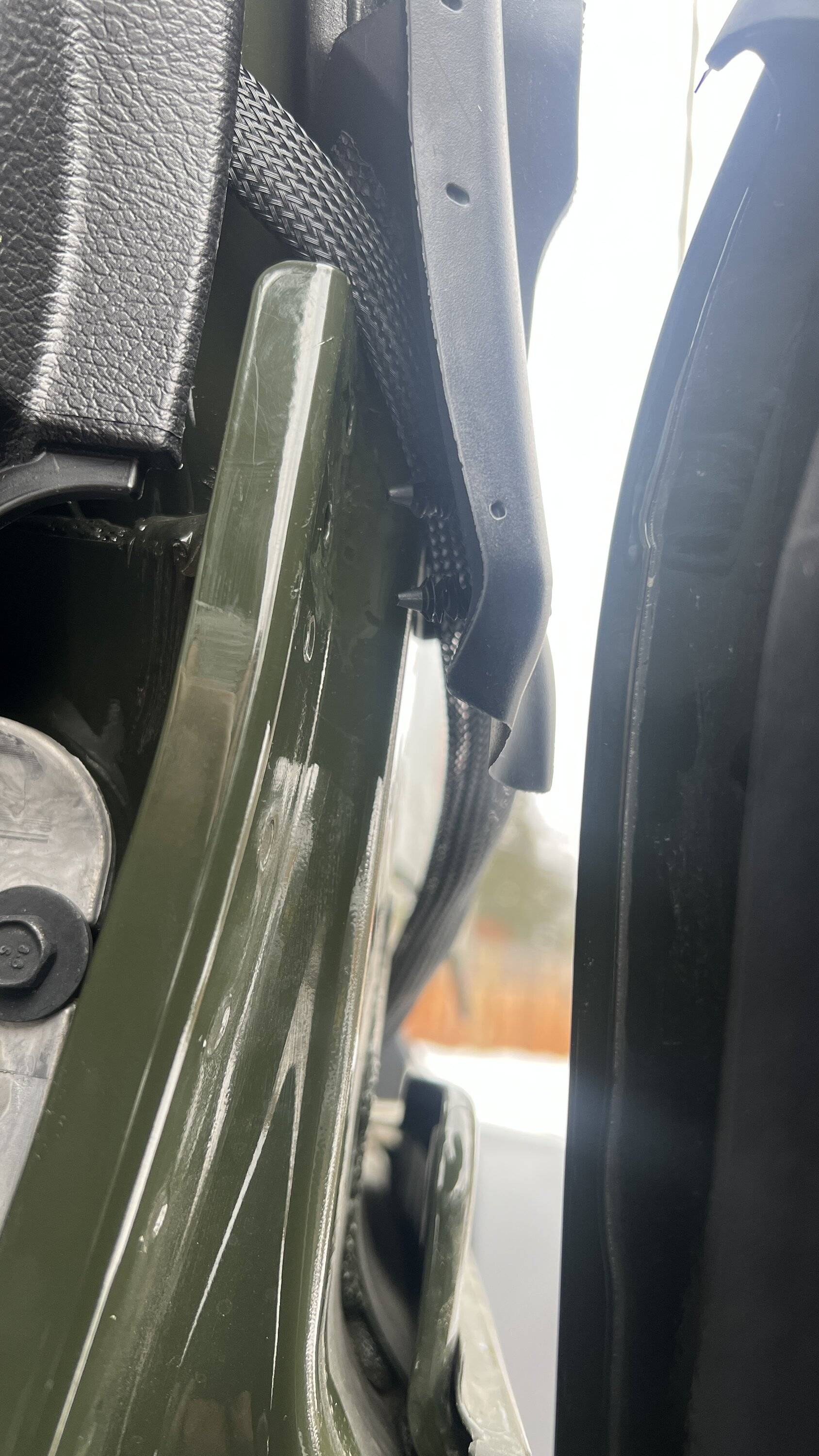
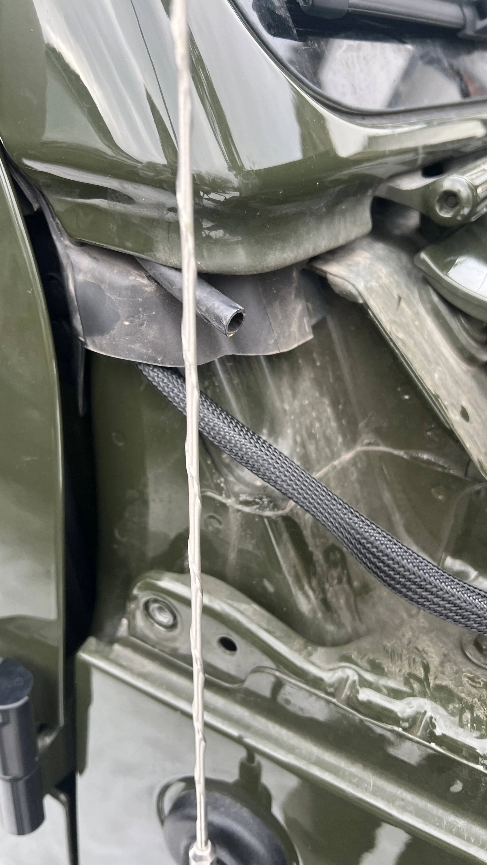
The rest of the wiring was fairly simple. I ran the data cable the same way as the GMRS on the drivers side - only on the passenger side. Hopefully there will be enough room for the CB coax as well. This was the easiest method and I couldn't find a firewall grommet when the battery box was taken out. I actually prefer this method as future repairs/replacement is much easier. The drivers side grommet that most use is not available as it already has wires going through it for the switch pro system, the 12v engine on signal from under the glove box, and power/ground wires for future additional in cab dome lights. The cable relatively easily passes under the weather seal.
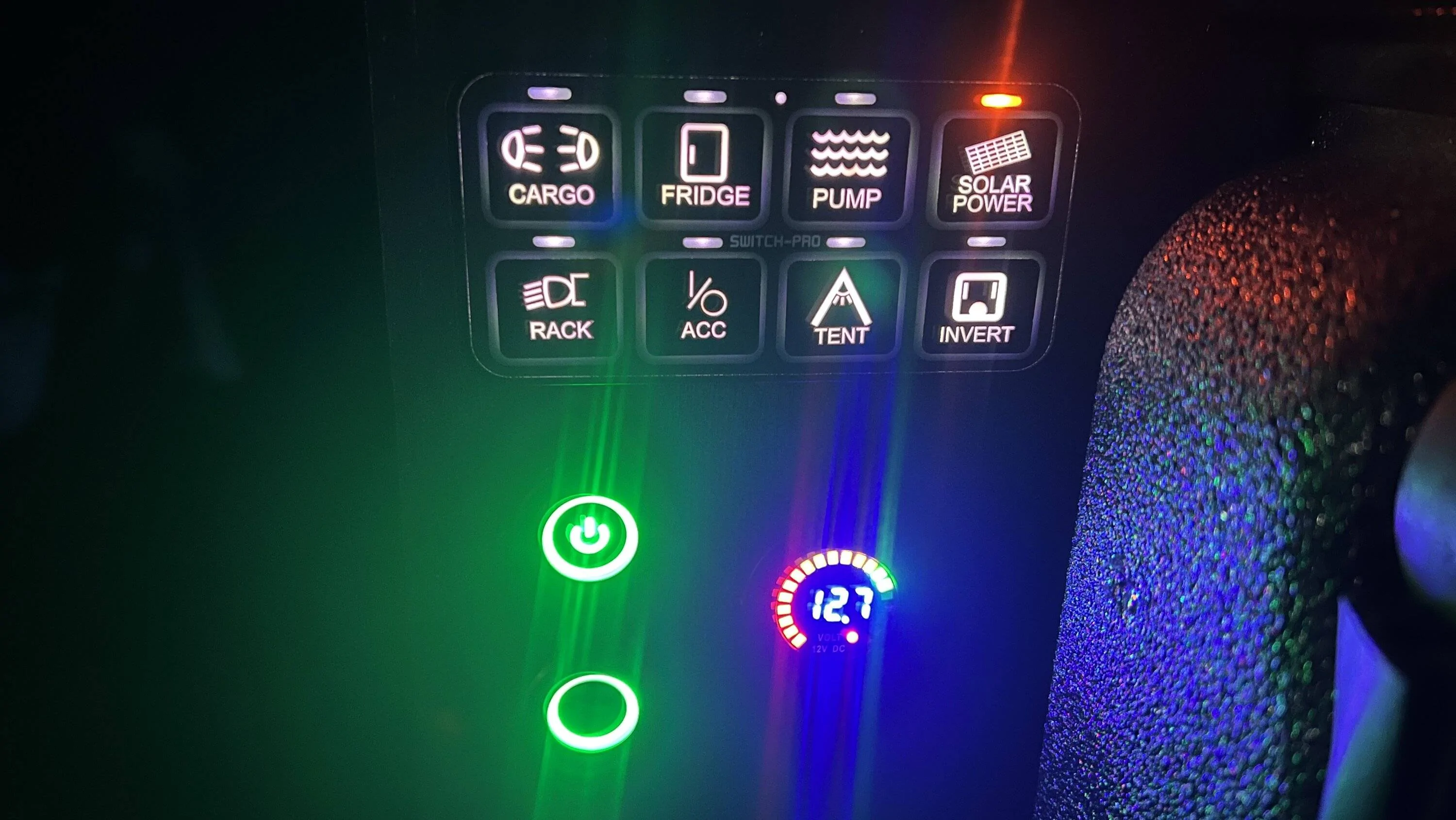
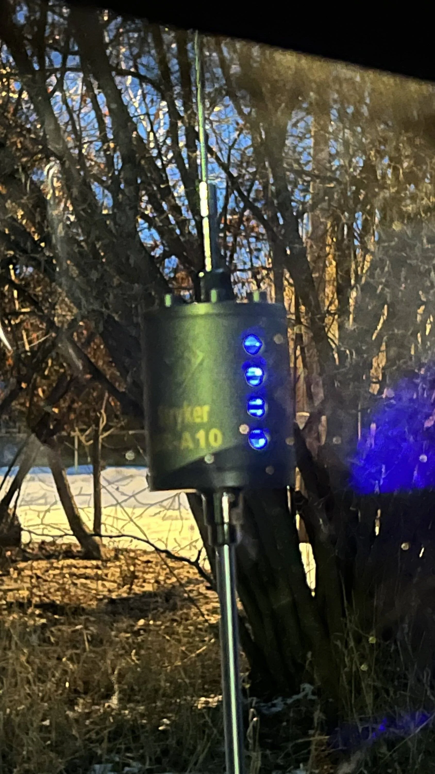
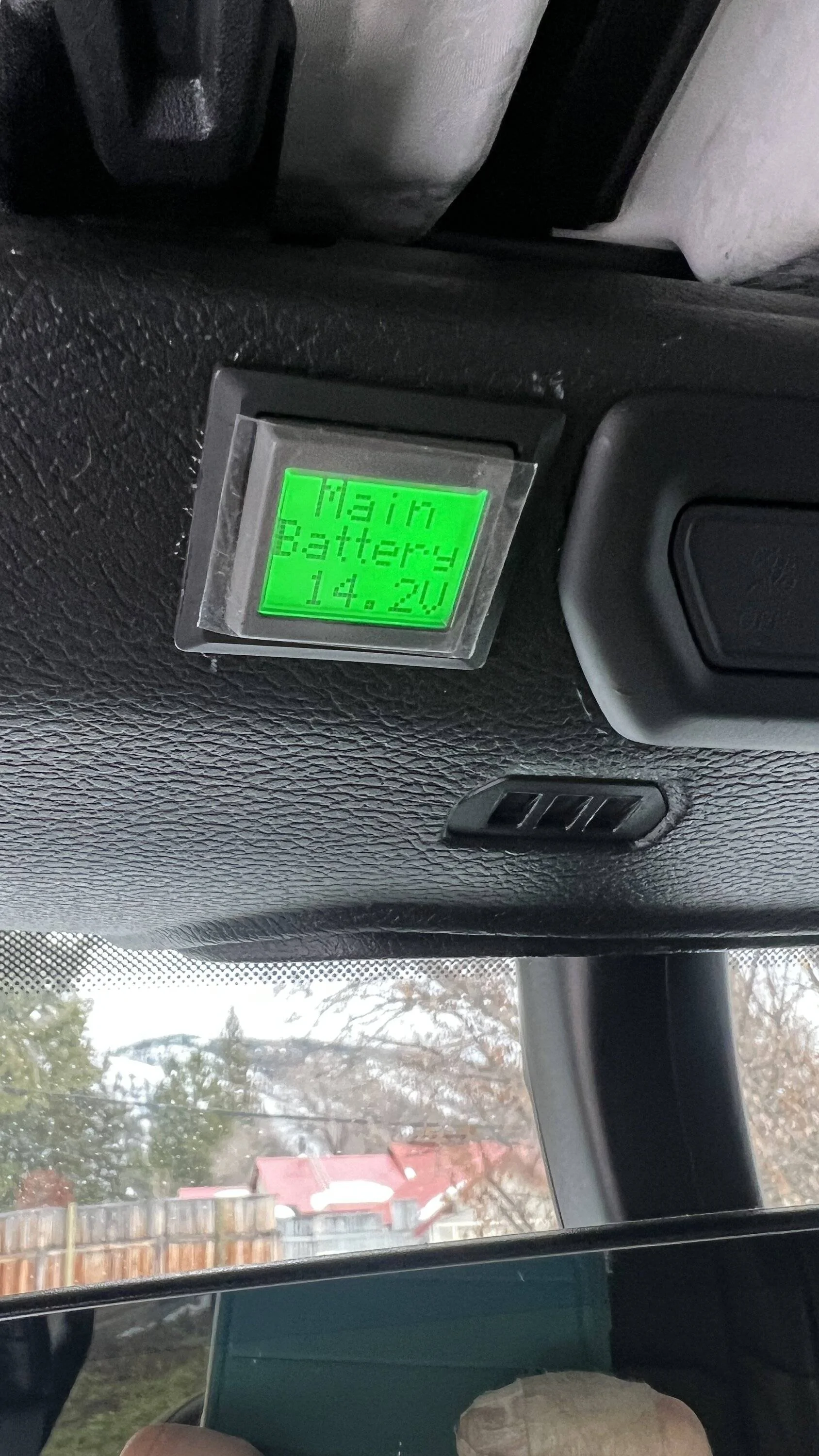
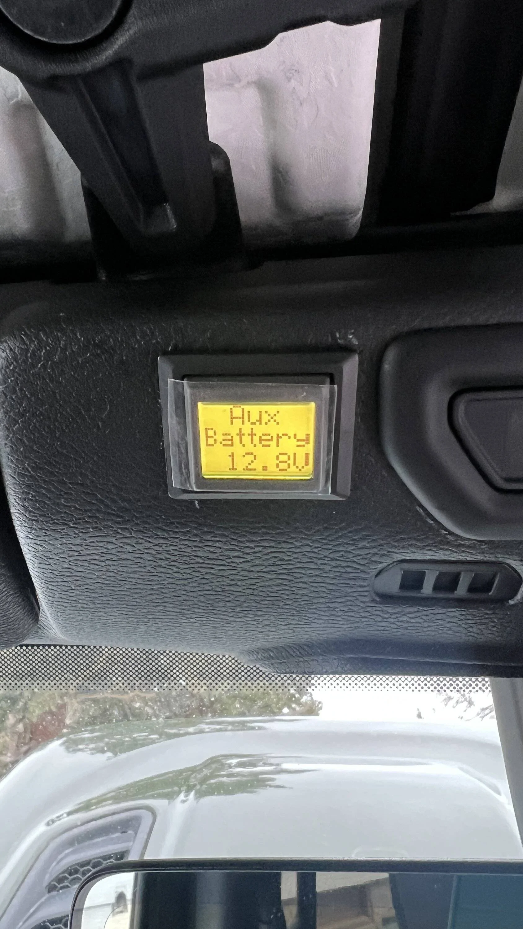
The rest of the cable simply routes to the Genesis system and plugs in with a weatherproof twist lock connector. The screen is pretty sweet. It's easy to see battery voltages of each battery, turn the auto connecting combiner on or off, or 'boost' mode which just forces the batteries to be combined no matter the voltages.
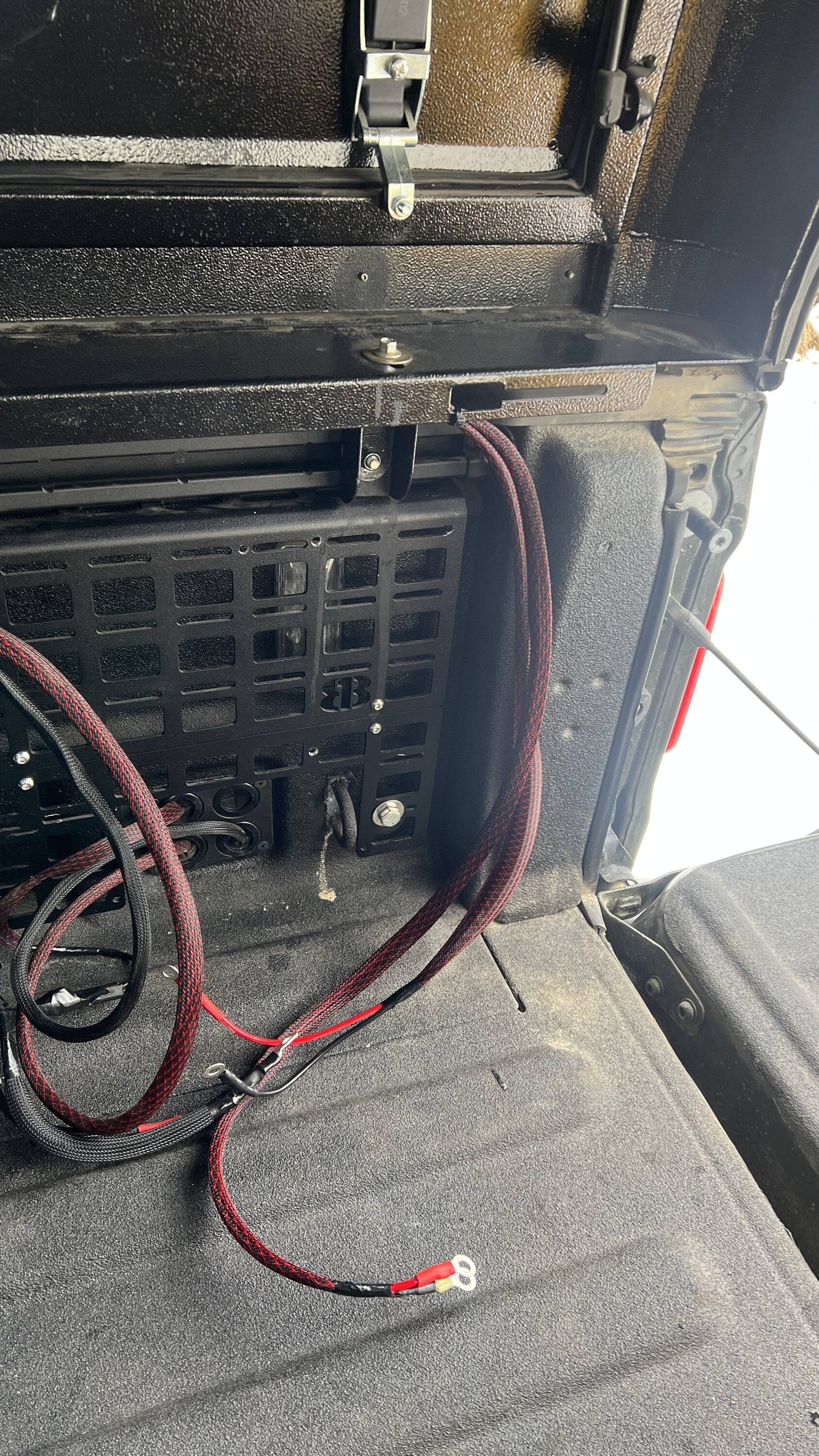
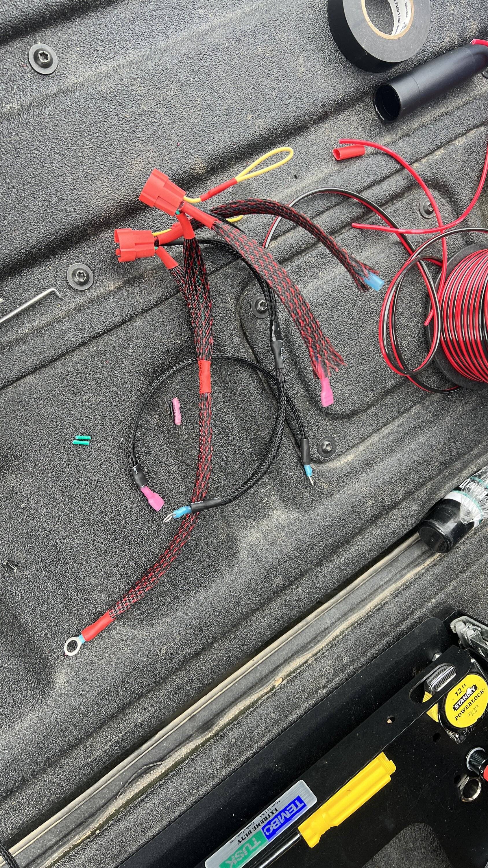
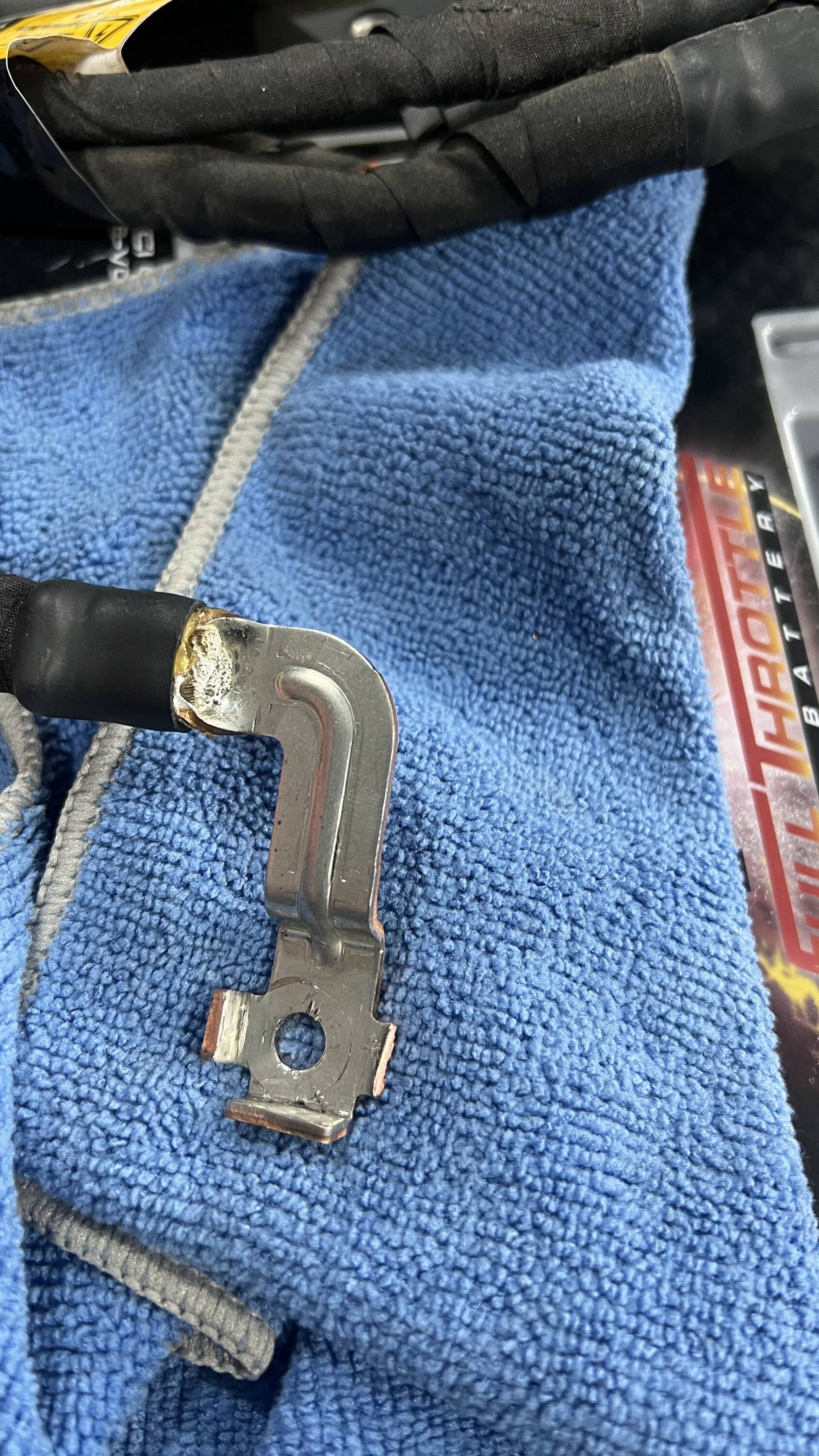
I also took advantage of being under the hood to clean up my mistake from Friday and find a decent place to store the factory aux negative battery cable. And, put some lugs on the 4ga wires going to the bed as well as put new lugs and electrical connector on the ARB in preparation of hooking it back up.
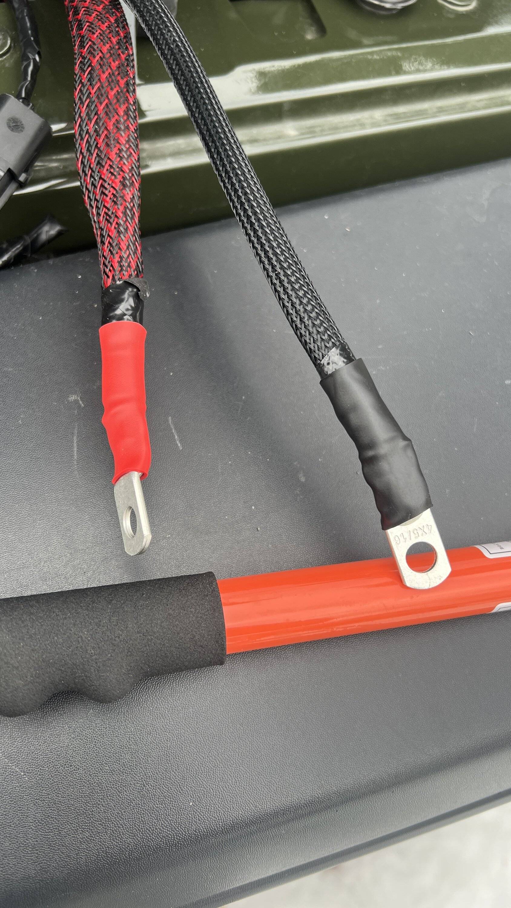
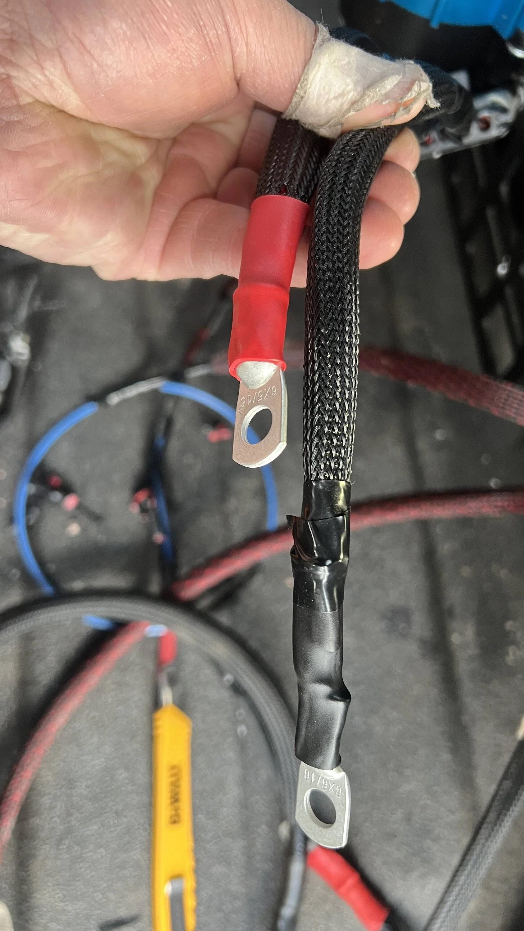
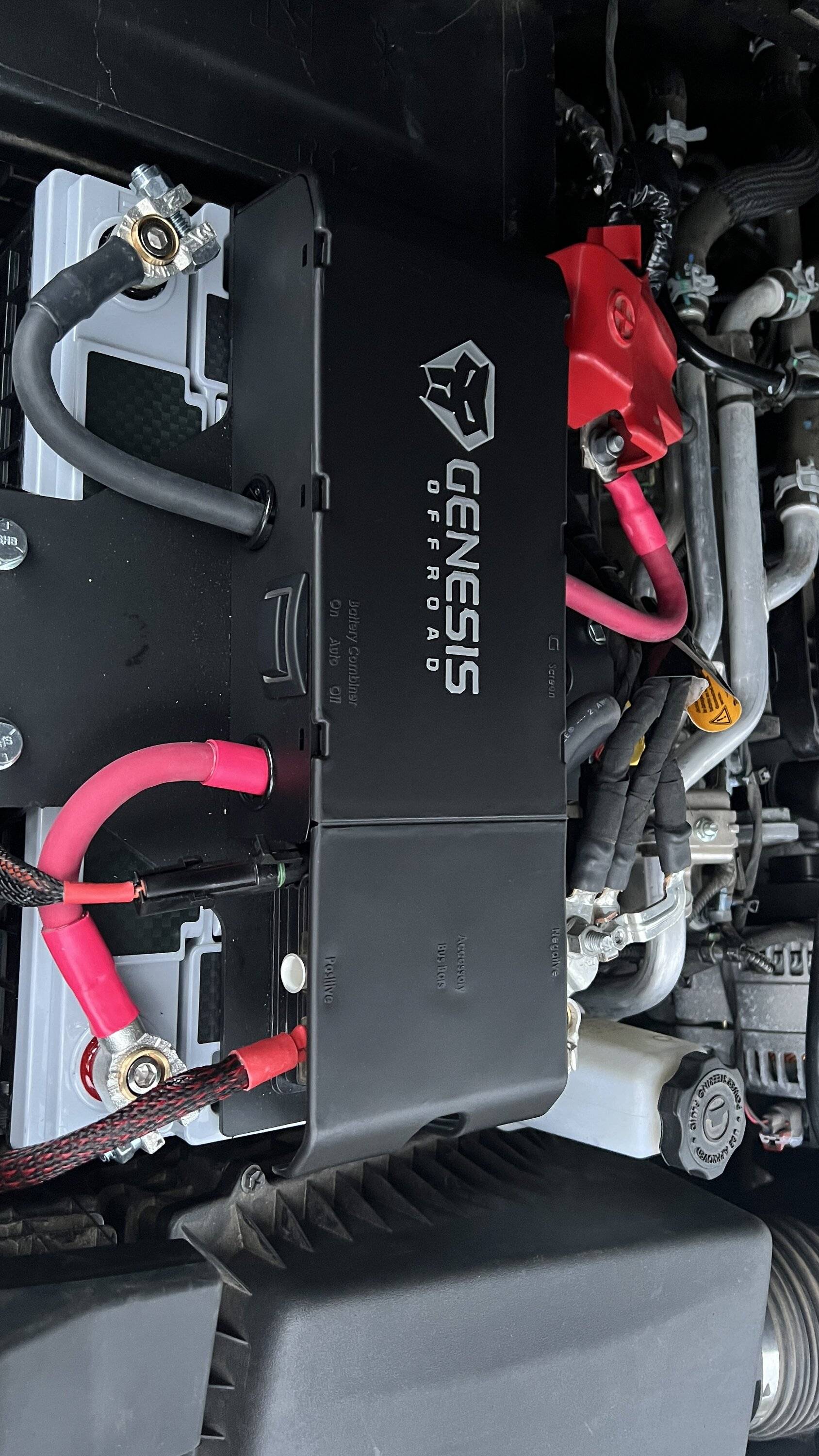
Looks super clean and I definitely like this setupWell yesterday was a fun, monumental, and frustrating day in one.
It was the day of installing the Genesis dual battery kit - but...with problems.
So before anyone says how much I dont need it - the primary reason for me doing this kit was not actually to have a aux battery for camping. That is just a side benefit that works for me being in such a cold environment where an always on board lithium would not last. But the primary reason for me to install this system is to get rid of the factory aux battery, and have nice lugs to attach accessories to. After seeing how many people are having troubles with their aux batteries, and the difficulty it is to replace them - I wanted something significantly easier to replace if needed. The Genesis provides that for me.
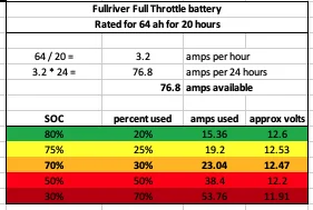
And it's a good thing because testing the factory battery and aux battery after removal revealed the larger system battery was sitting at 12.5v and the aux was already at 12.3v. Granted I dont drive a ton to commute, and it has been sitting a lot lately, in the cold, but at less than a year old this is what I was worried about with the factory system.
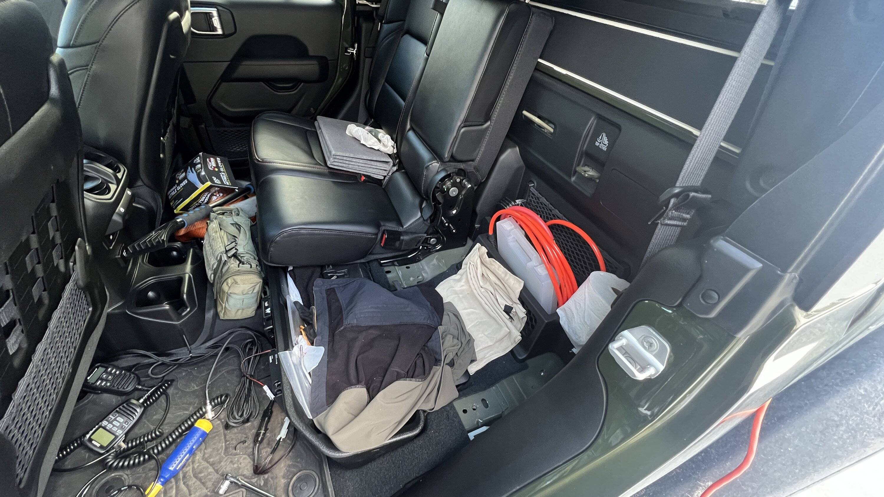
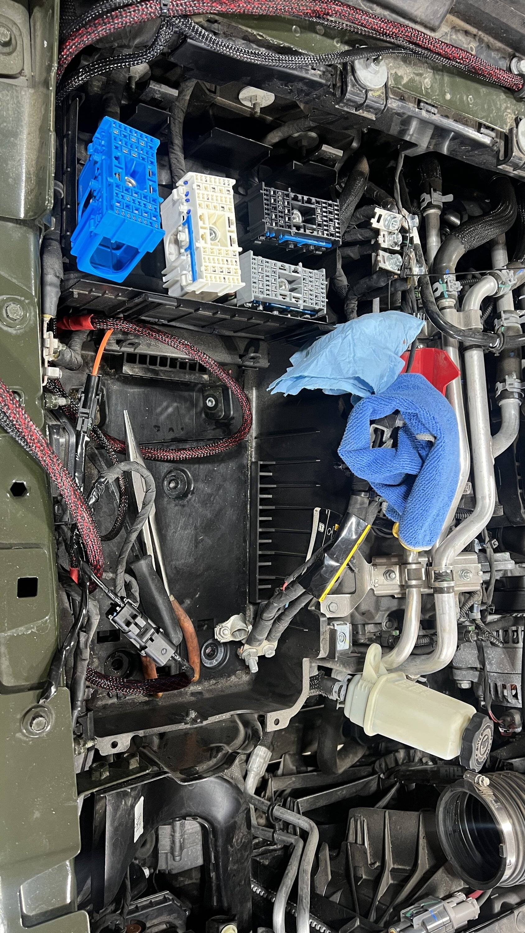
Removing the factory batteries and tray was relatively uneventful. Although I took careful note to keep in mind where everything is and went as I did not want to have issues reinstalling - well... I did anyway. Being careful, using hand tools, and chit-chatting with a friend who is letting me use his garage, the removal took nearly 4 hours. I can't imagine having to do this every single time to replace the factory aux battery - thats insanity.
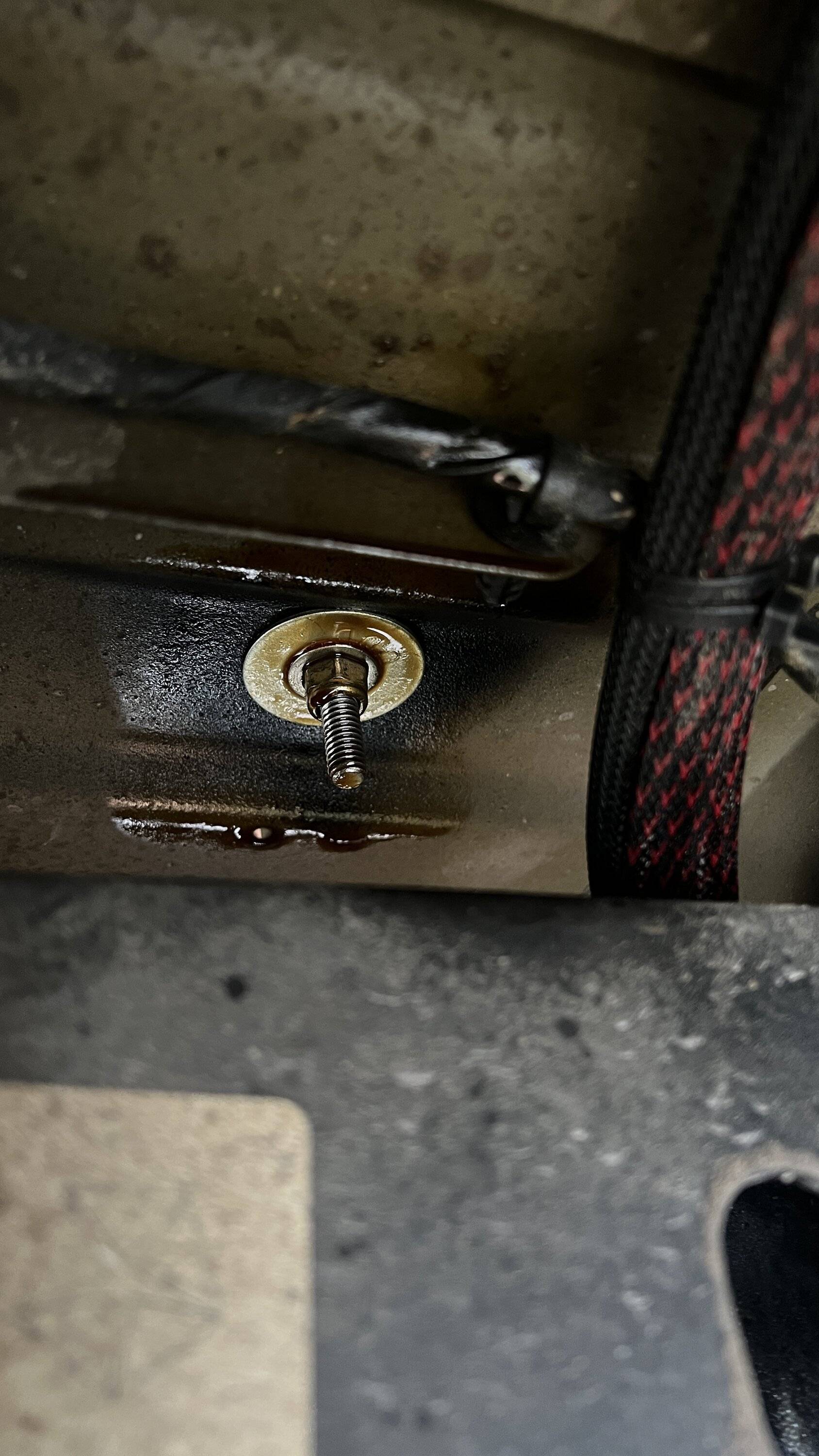
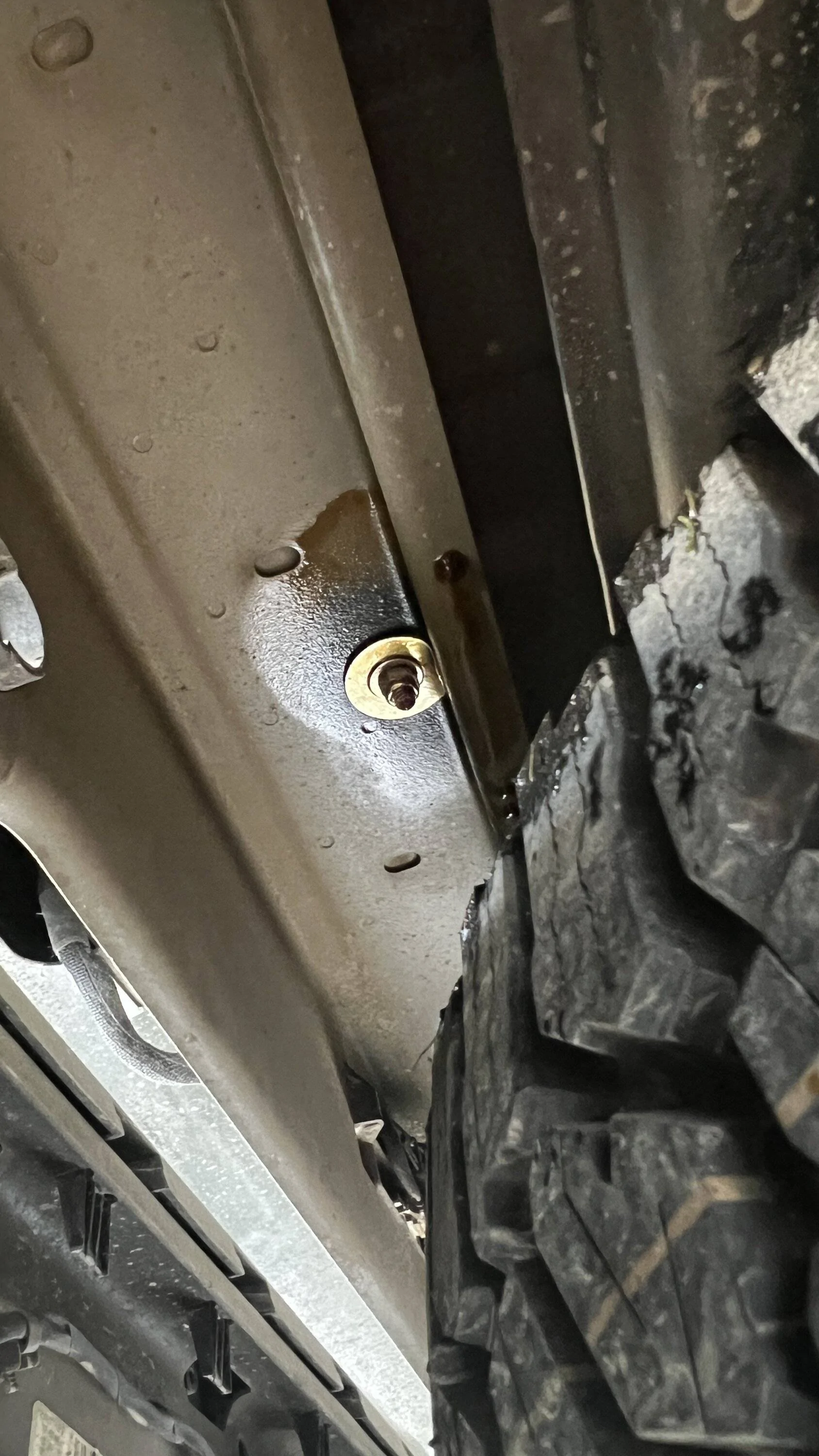
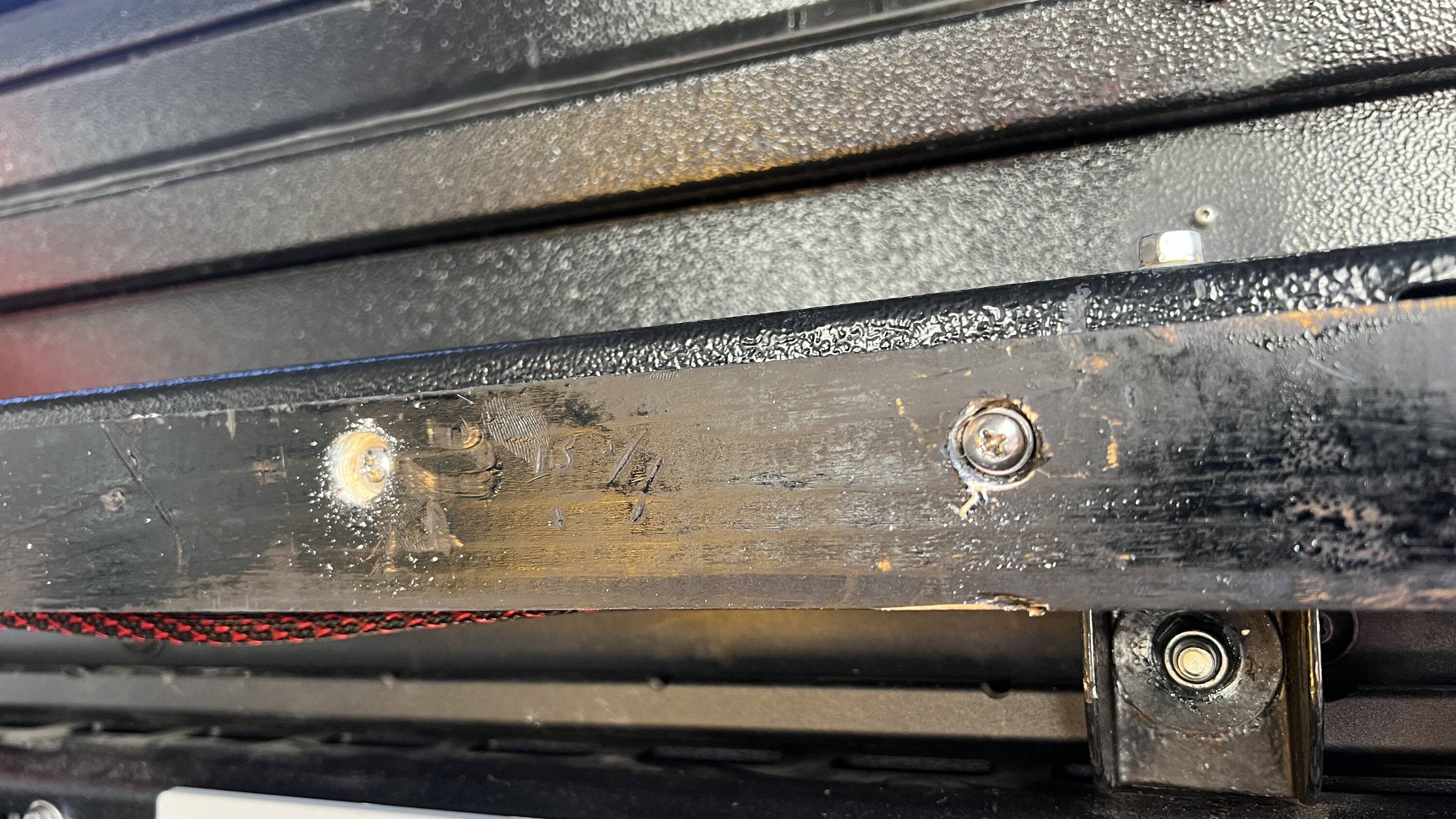
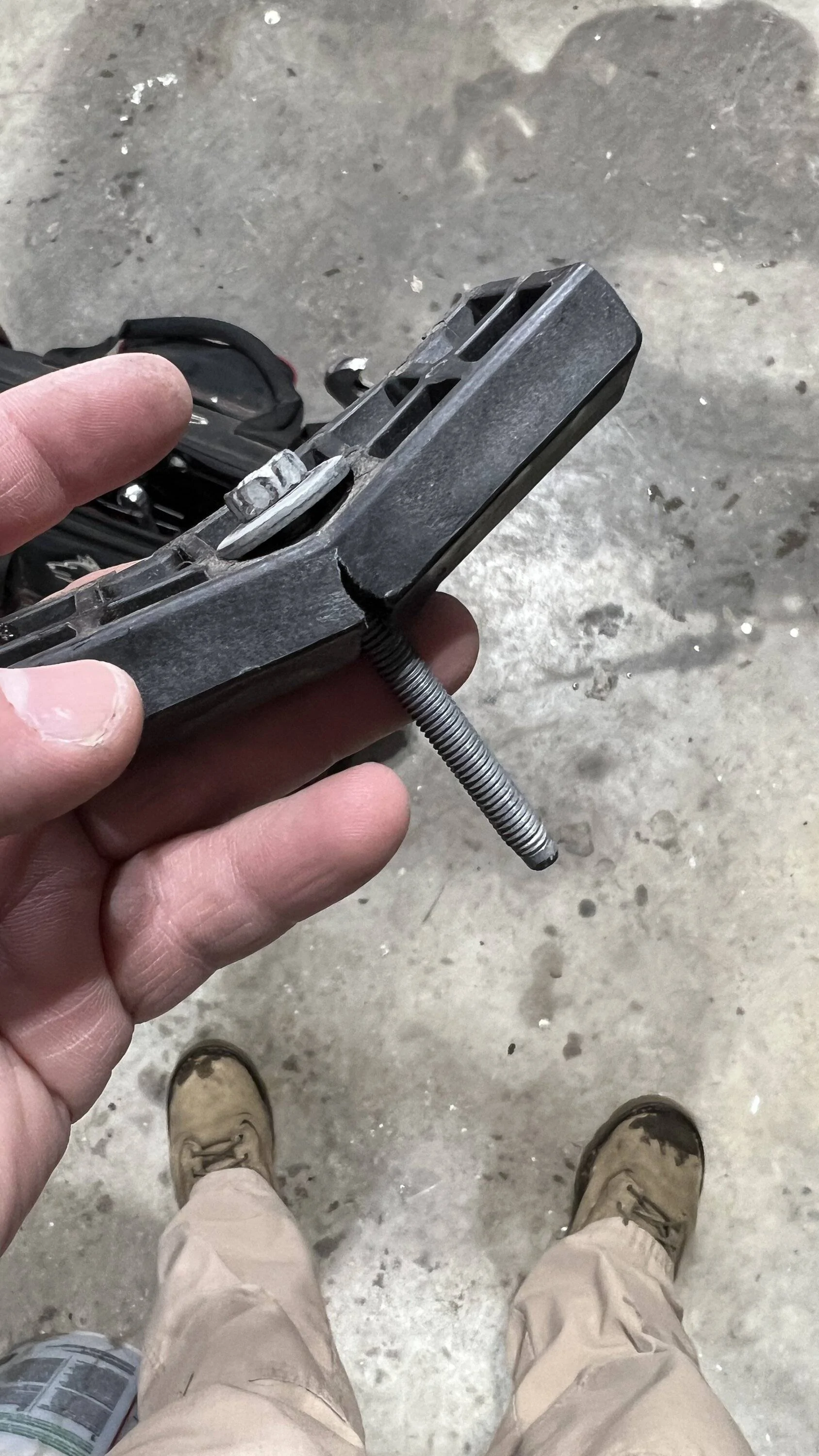
Oh and I also saw this - looks like the factory way overtightened the hold down bracket. I have not touched the battery components since purchase.
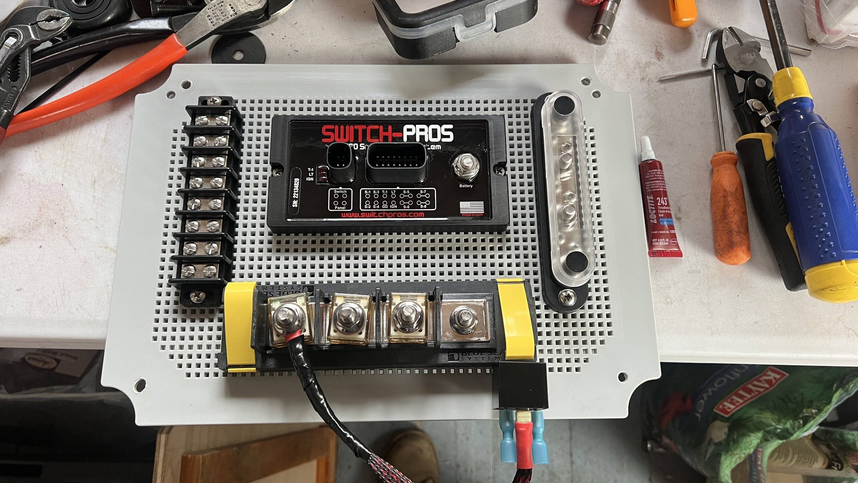
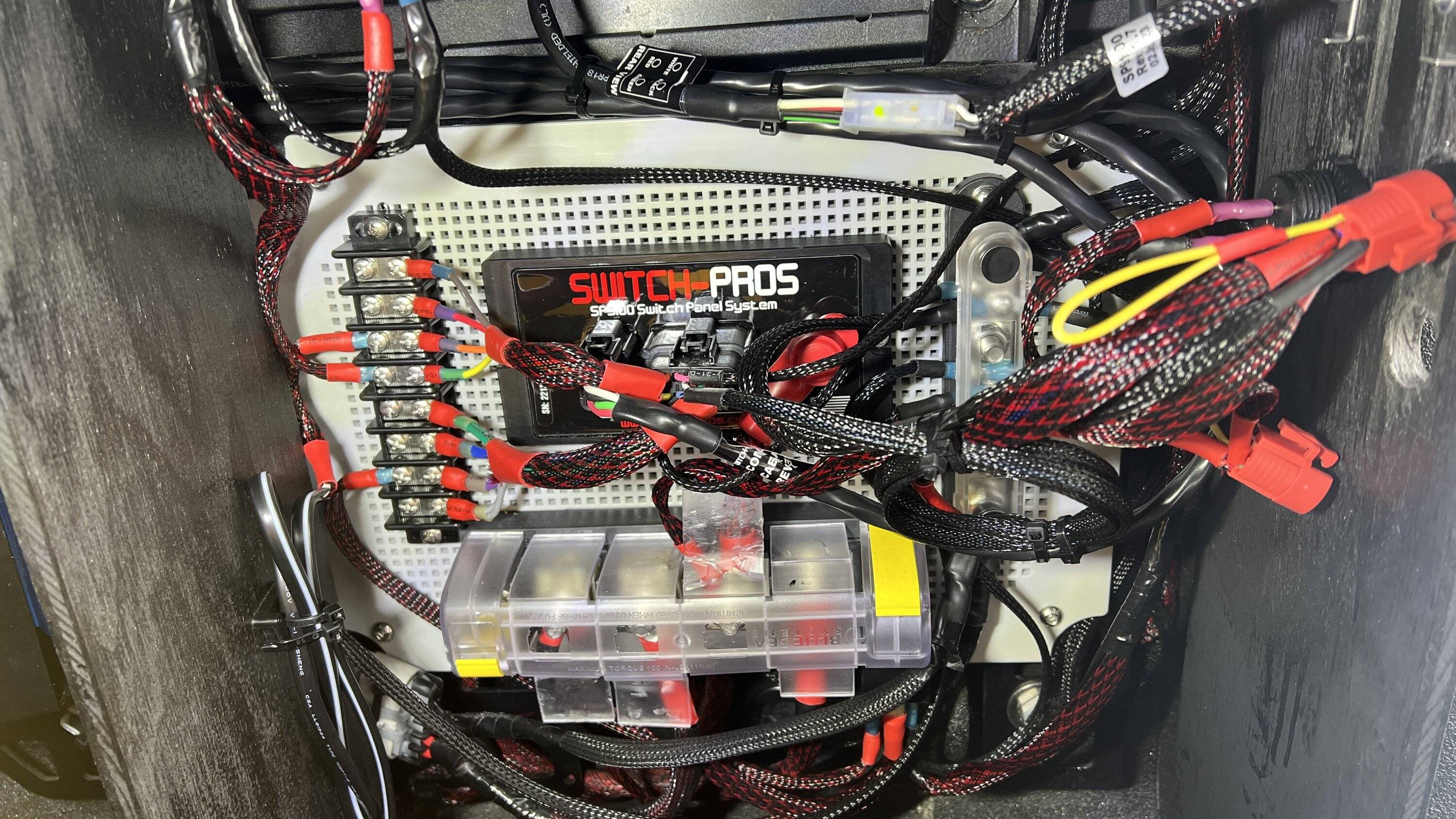
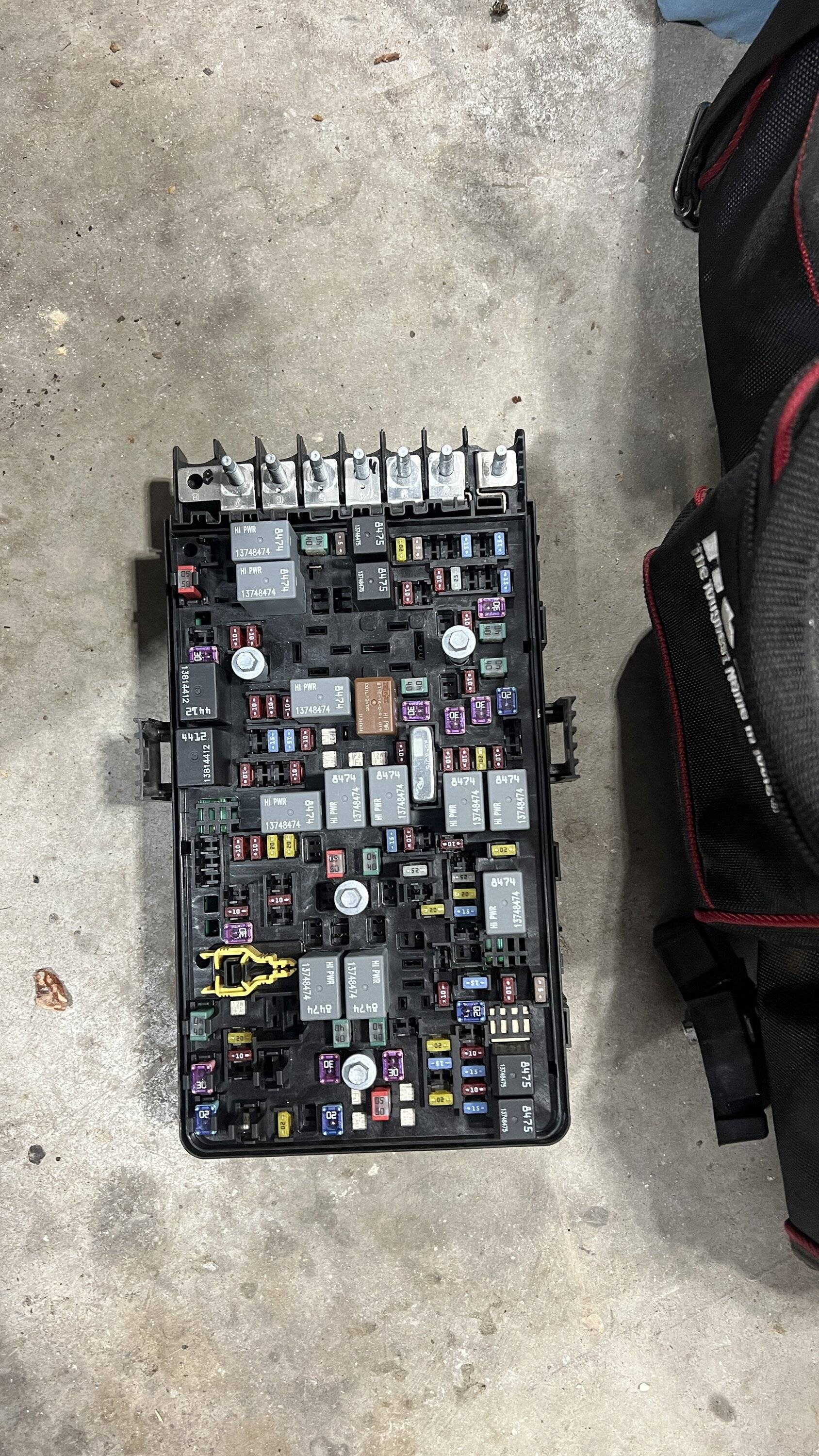
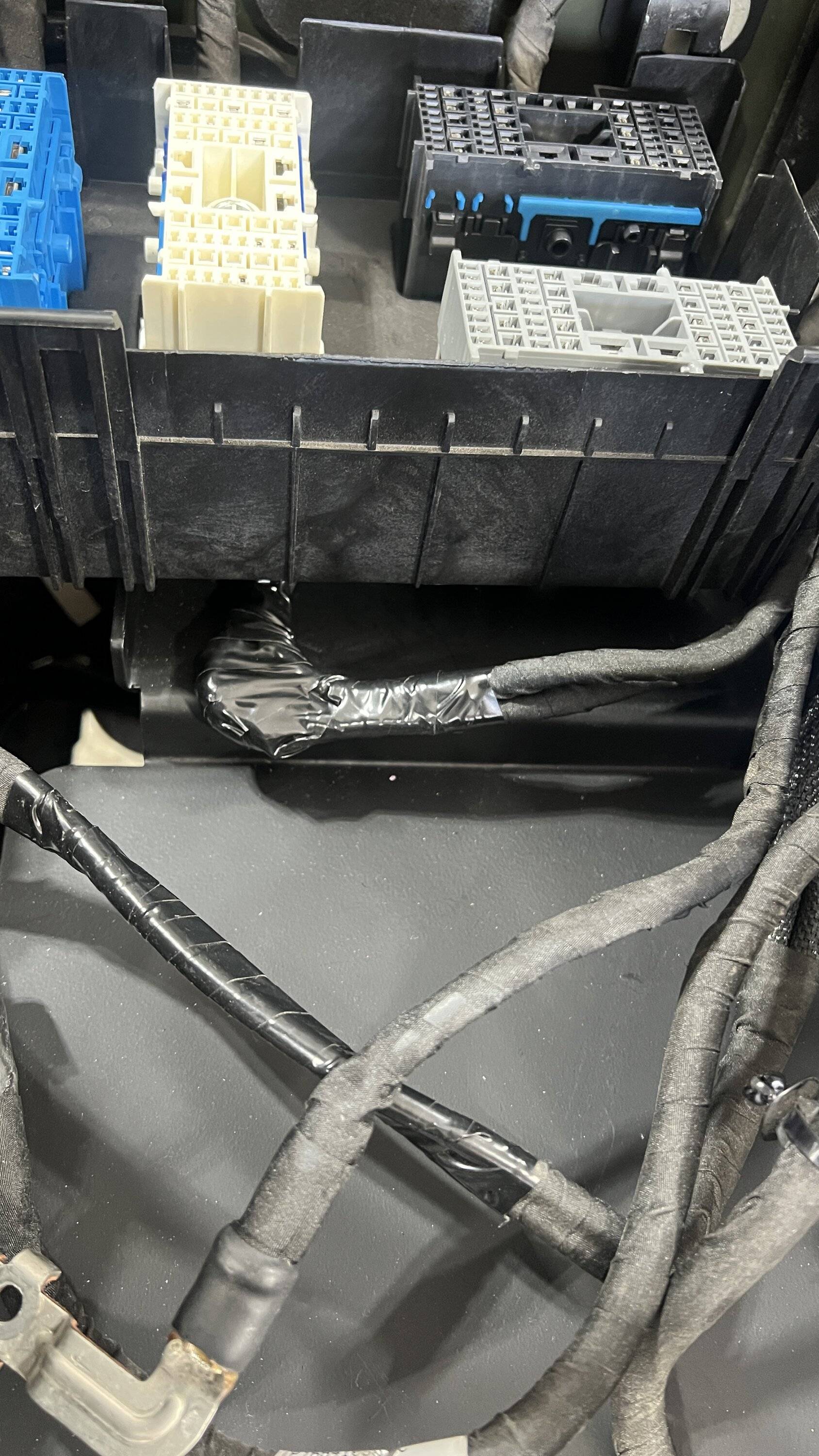
You can see that post 4 and 8 are unused in mine. I would assume #4 has something to do with the rear bed inverter and I dont have one, just the in cab version. I labeled all the posts just to make it easier
Being sure to protect the positive wires as much as possible - I wasn't sure if any of the others were also hot but based on other videos I have seen they seem to not be.
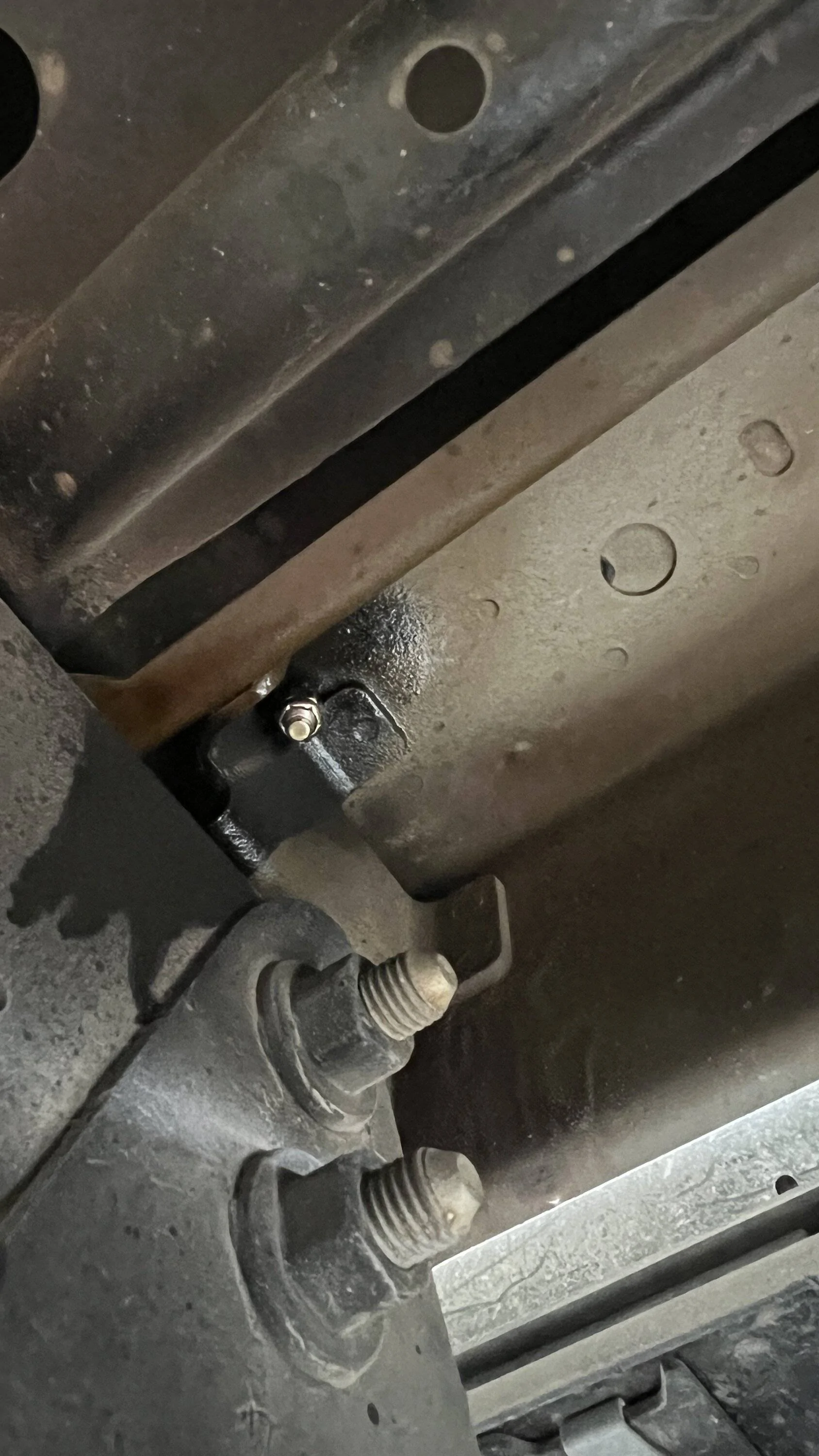
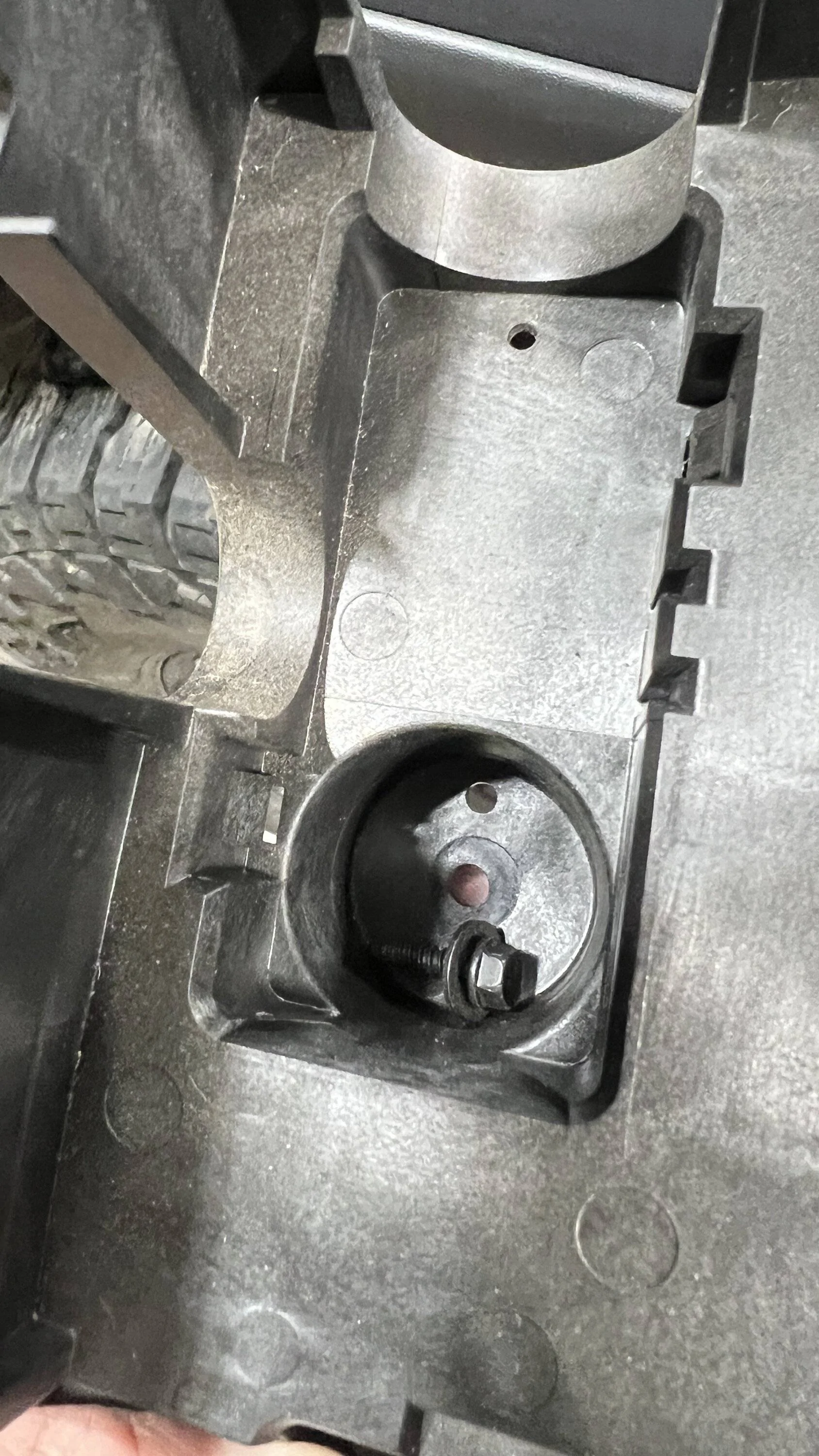
There was another change sometime half way through 2021. The Genesis video shows there to be 2 bolts and 1 Phillips screw under the distribution panel to remove the box. Mine had a little 7mm bolt instead.
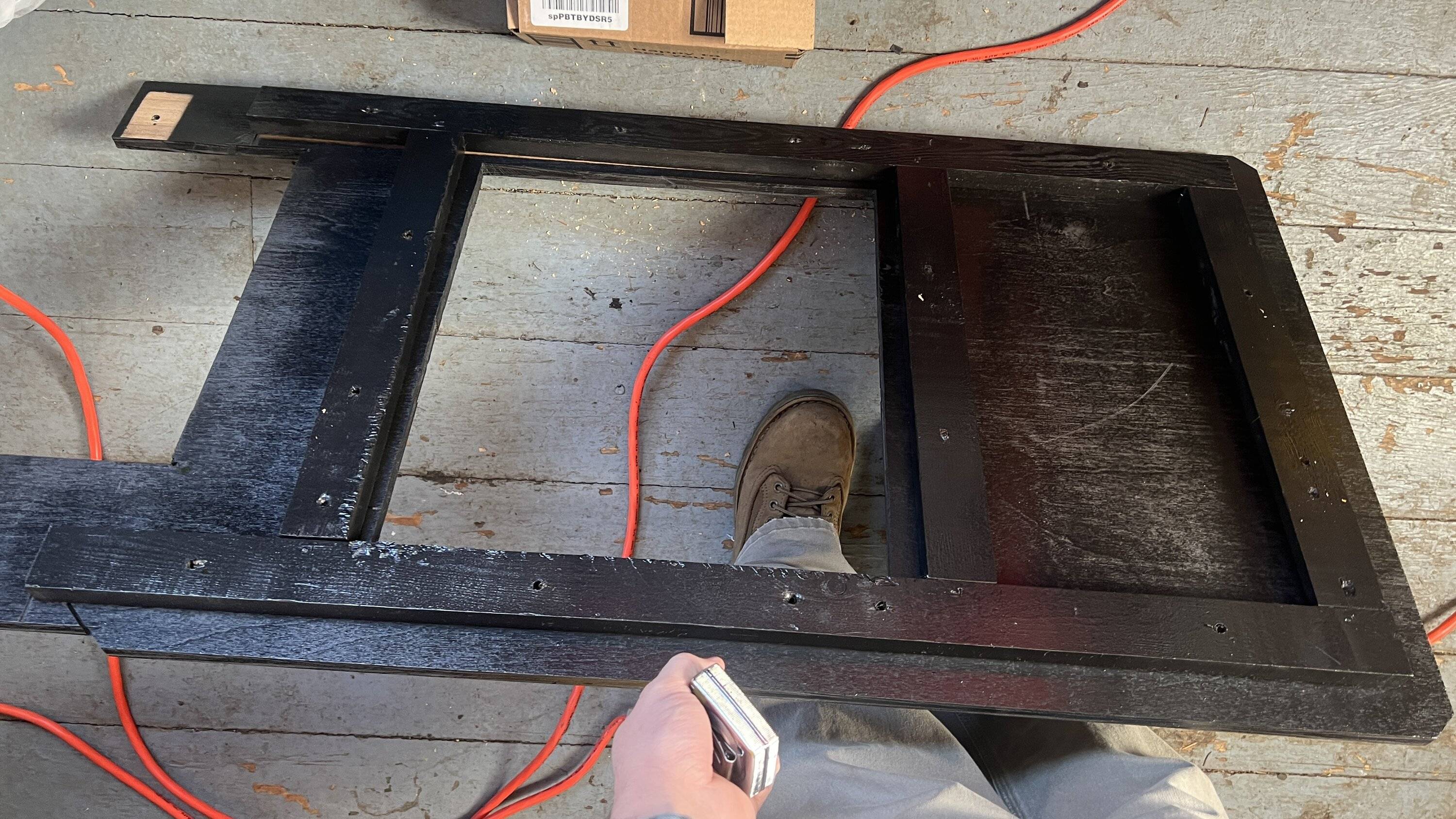
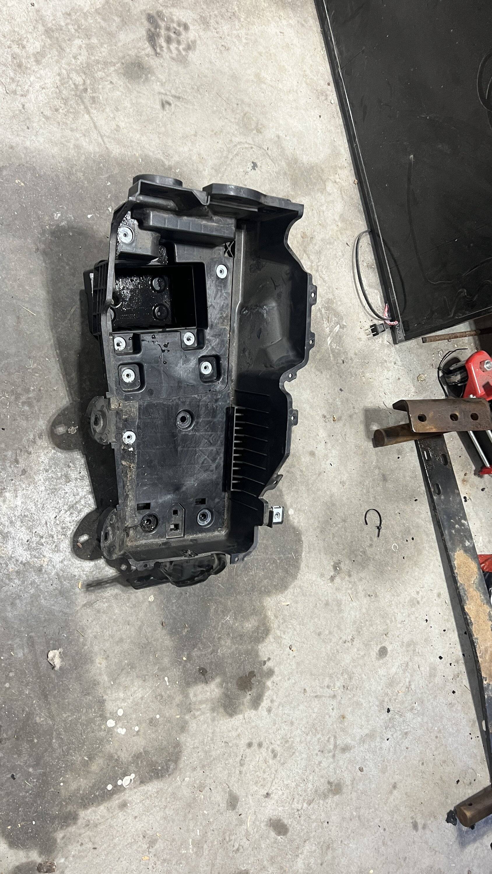
That tray was unnecessarily difficult to remove. It still boggles my mind this was actually considered a valid design. I know there is the method of going through the fender, but still, batteries are known replacement items - terrible design.
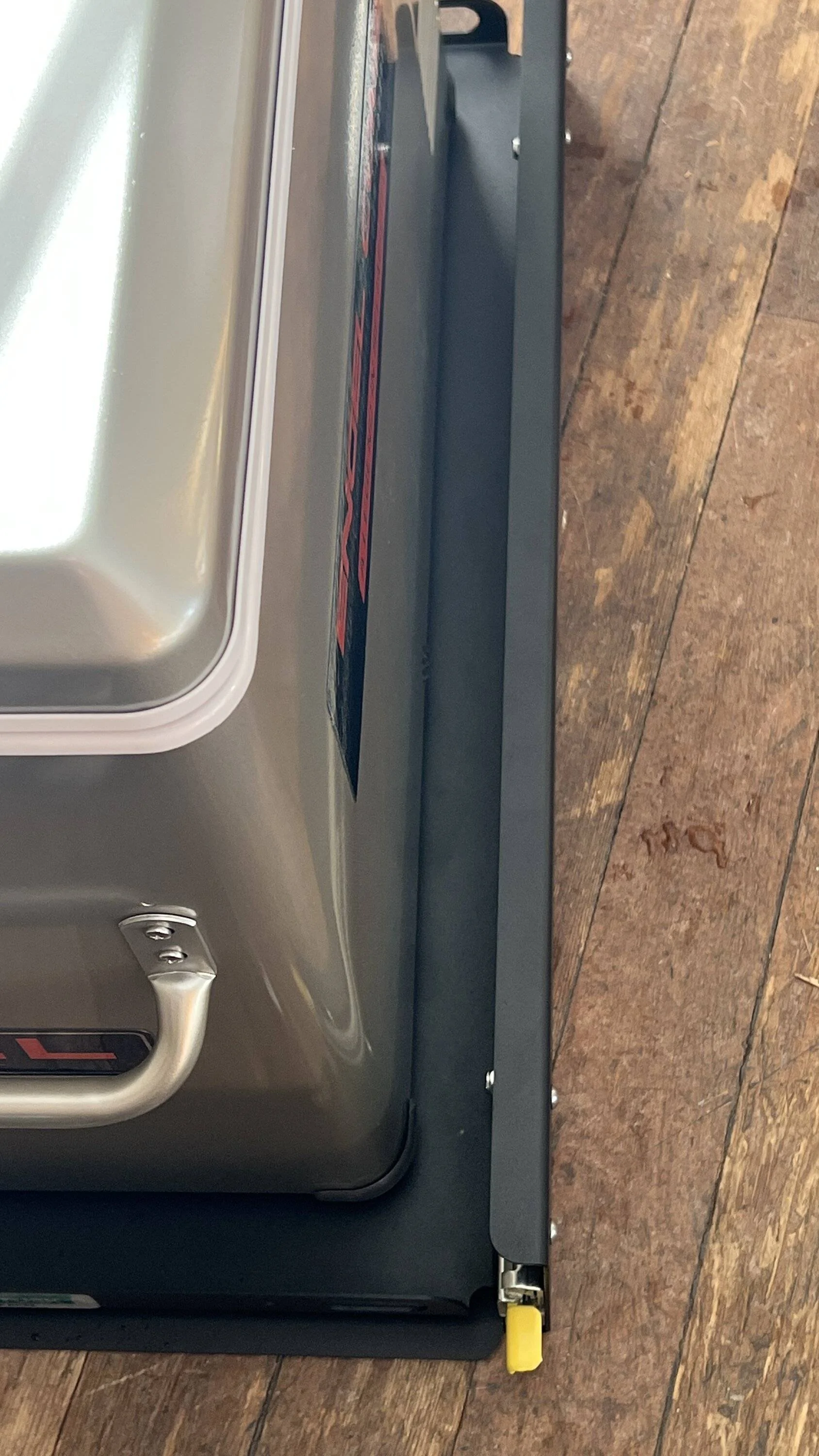
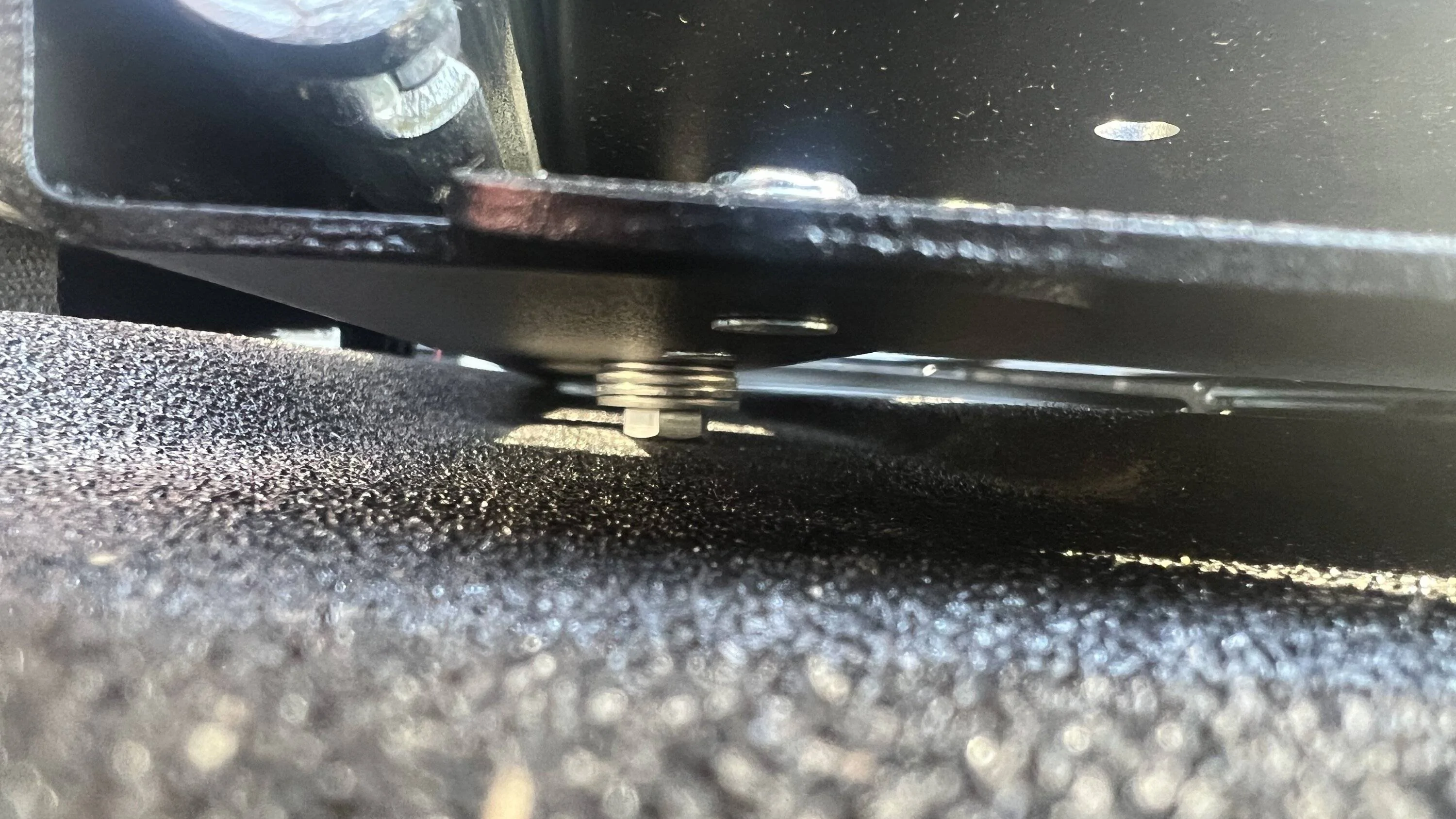
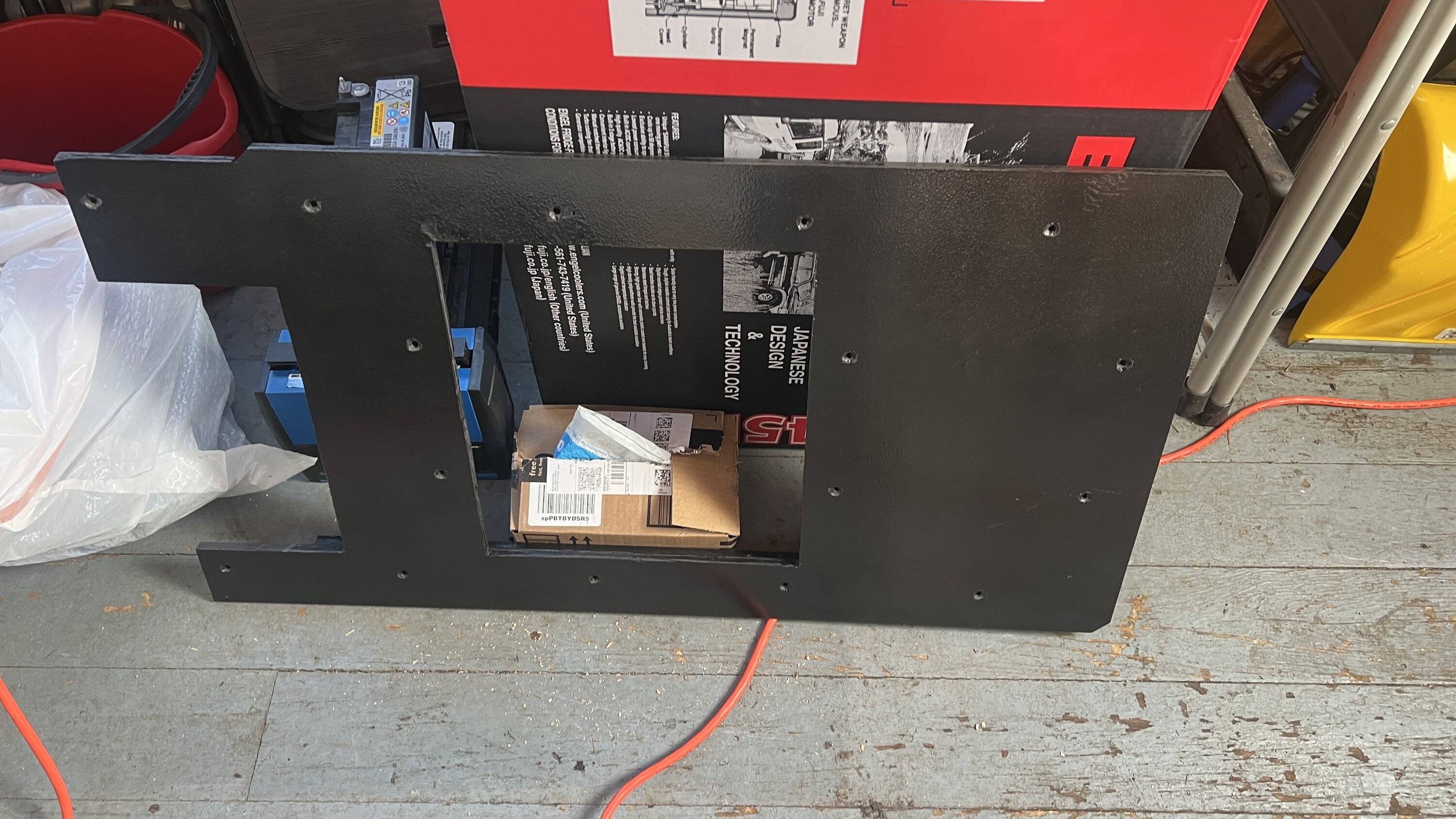
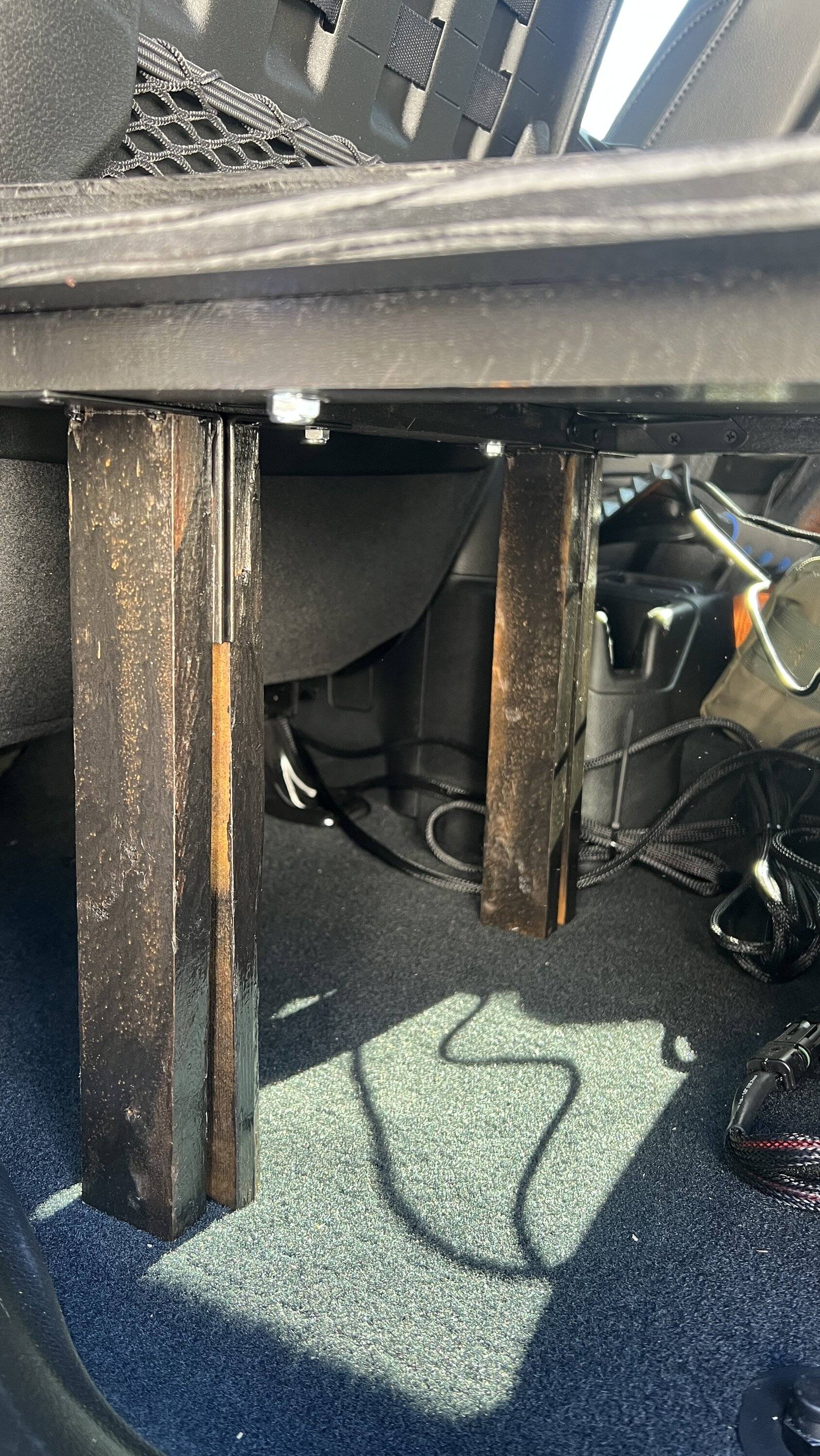
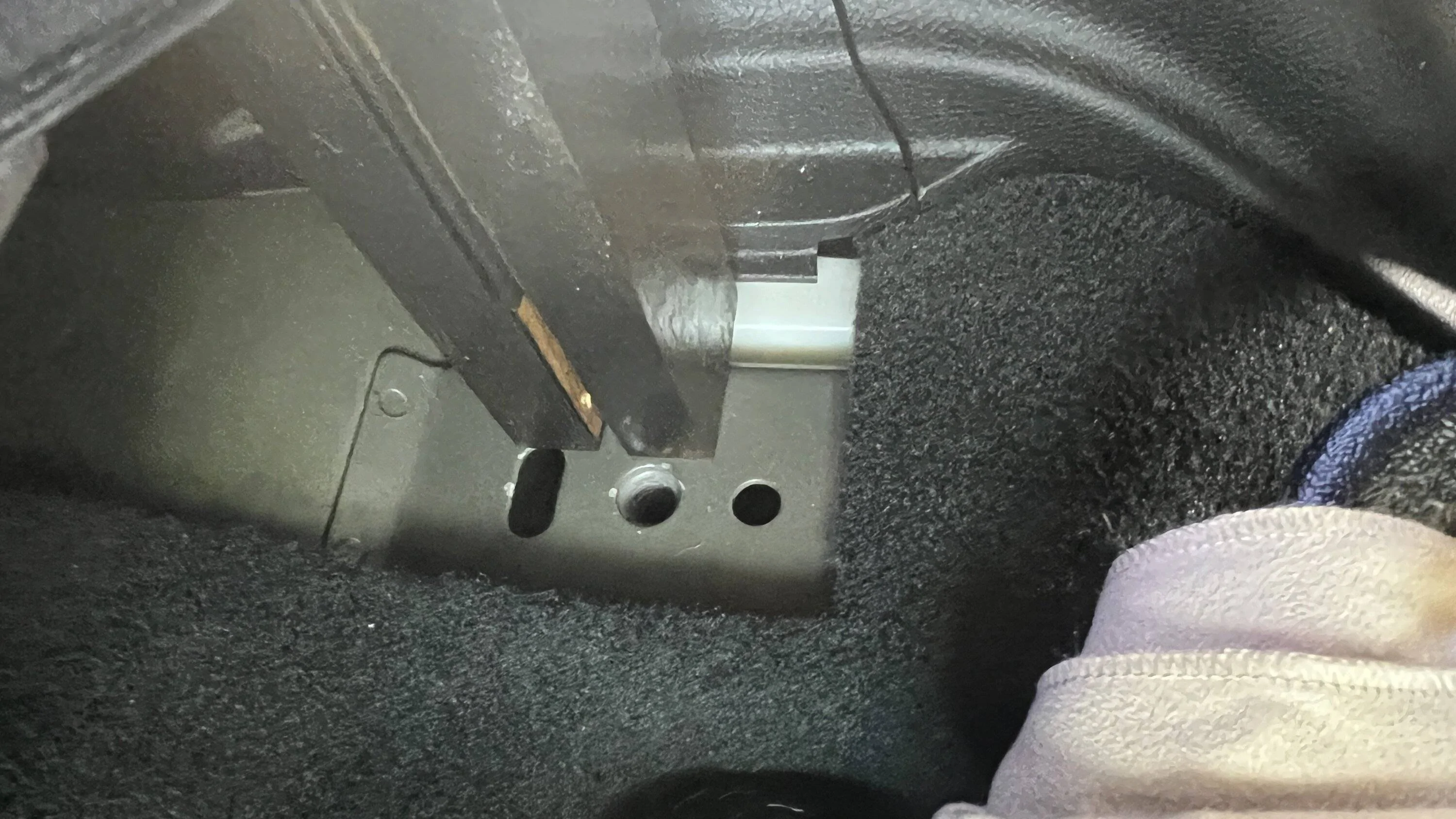
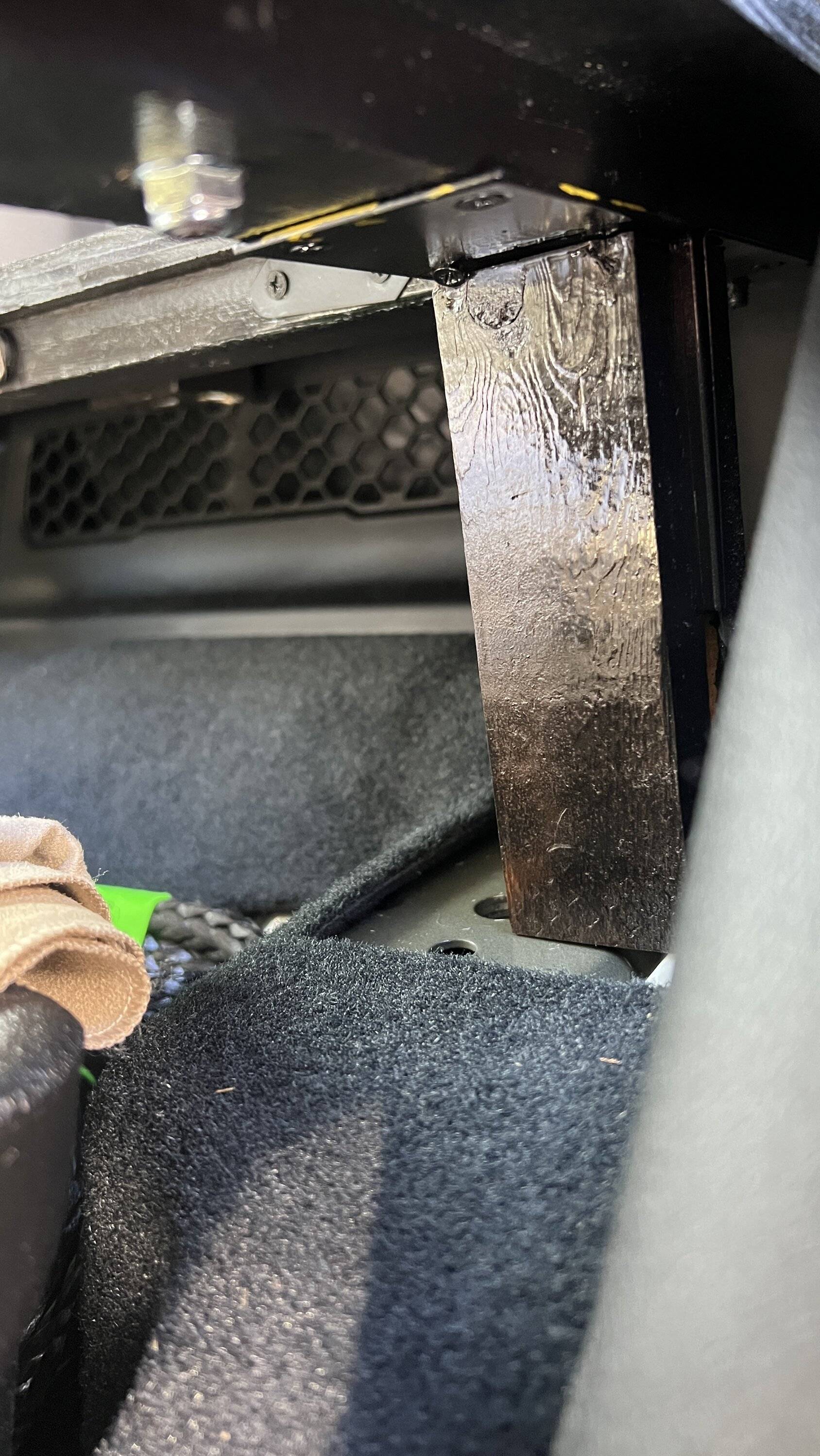
Now is when things take a turn and get interesting. The new tray went in relatively 'ok'. Although it still didn't fit perfectly. There must have been even more changes between 21 and 22. There was a bit of a gap at the front of the tray where it uses the two bolts to secure it next to the air box. I was very surprised to learn that Genesis only designed it to use 4 mounting points. So I have a bunch of leftover bolts. I wish they would have designed it to be more secure. I'm sure it is fine, but it could be better IMO.
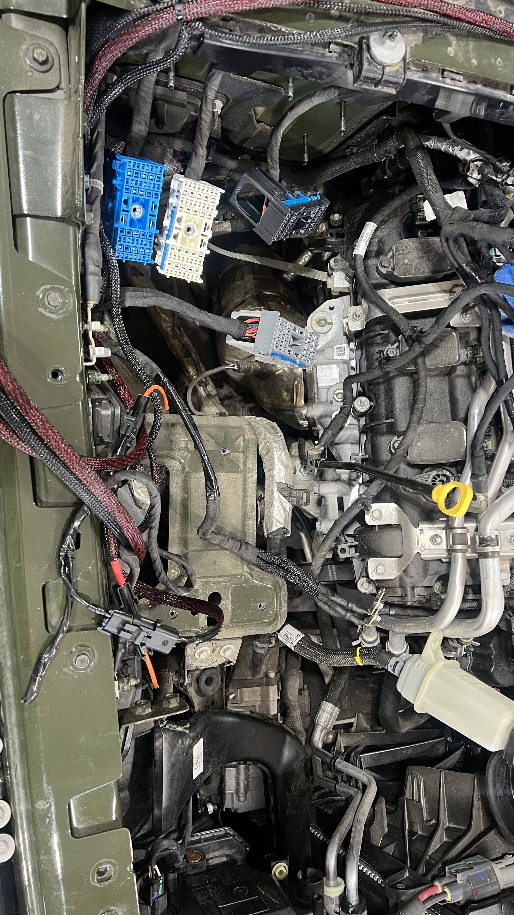
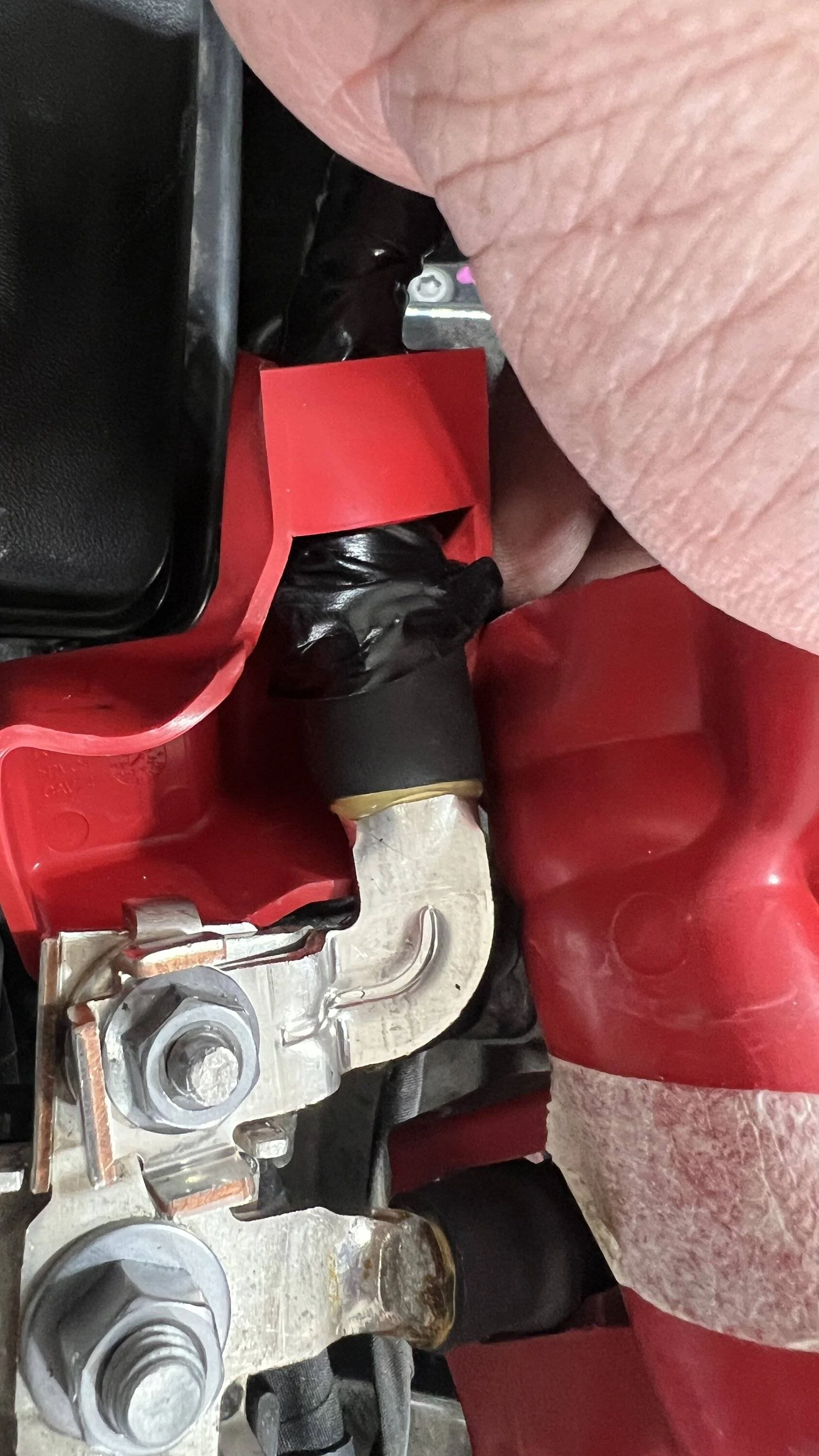
This is where my first mistake was made. I got mixed up thinking the factory aux positive needed to remain left off. DONT DO THIS
Continuing my mistake of storing away the positive cable
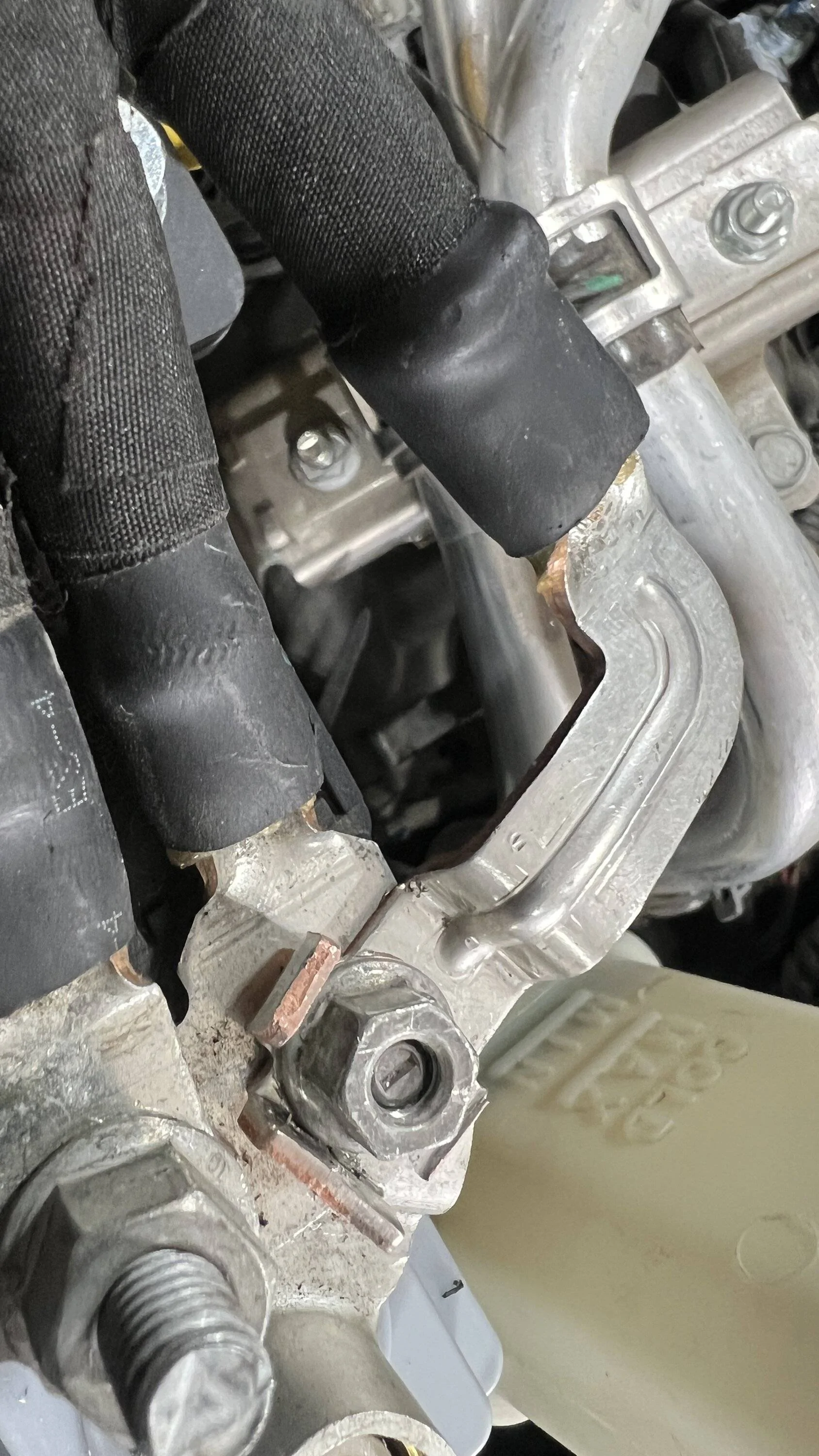
This was another mistake - after having read about others experiencing issues on various forums due to a change in wiring harnesses sometime between 21 and 22, I mistakenly thought the factory aux negative needed to be attached to the main negative. This caused about 35 minutes of frustration as the negative really did NOT want to go there. I pulled hard - hopefully no strands are broken internally. Eventually it did go, but clearly it was not happy. At this point I knew something just wasn't right. Did Genesis really miss this and not catch that there was a substantial change? Nope...it was all me and my lack of paying attention in excitement of having this system in.
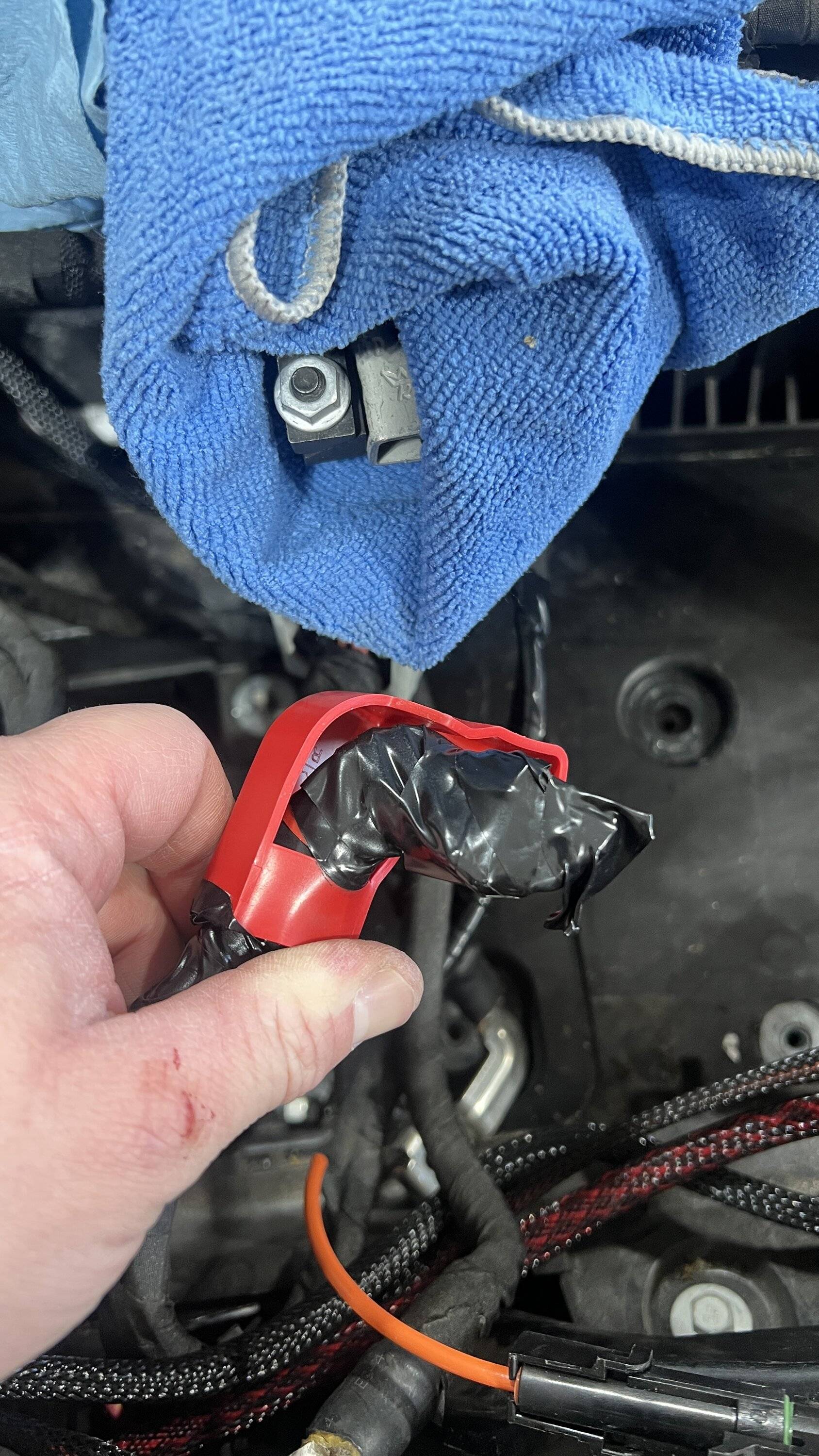
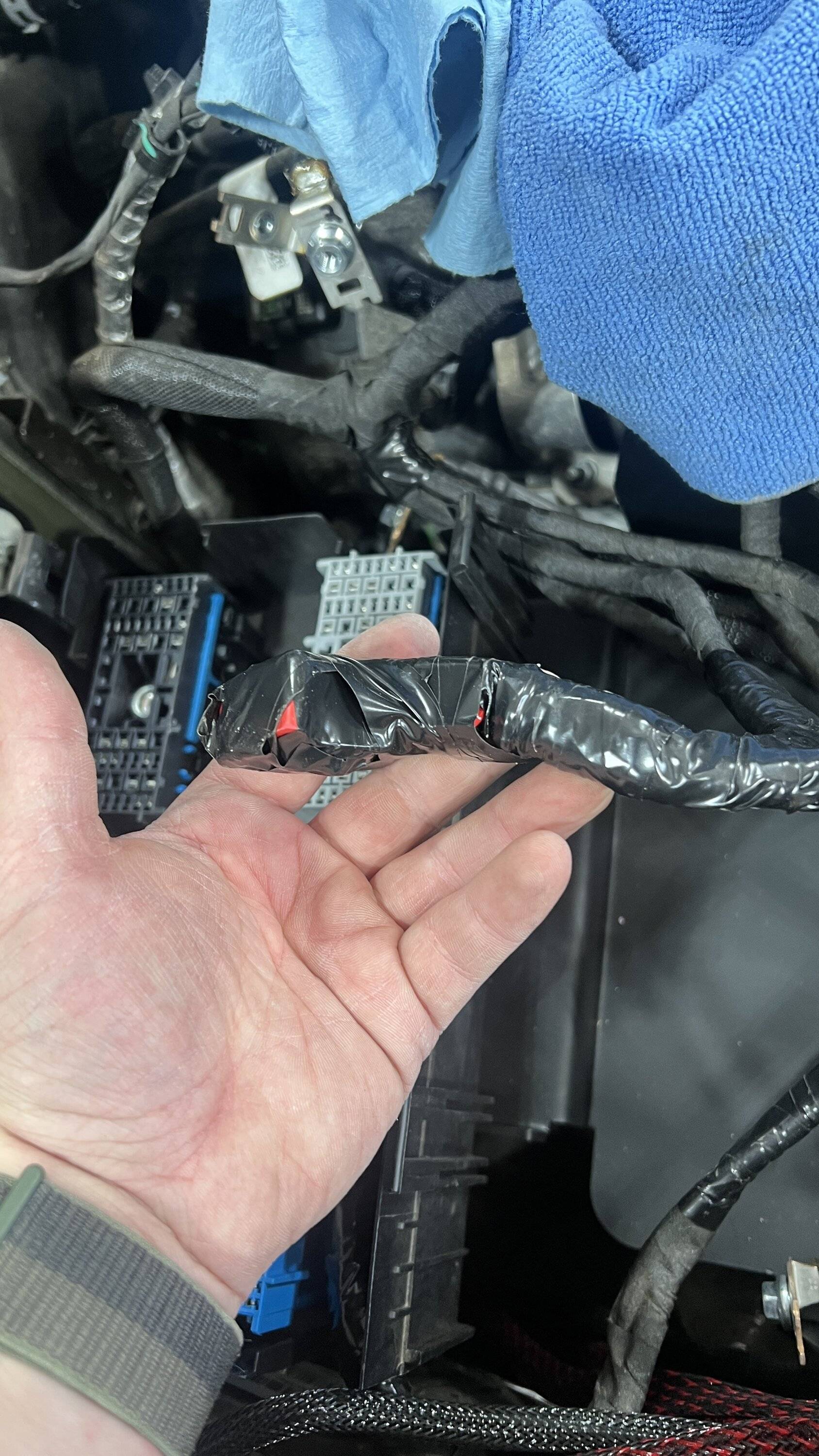
After putting the distribution box back in is when trouble began. Now - take note that I misunderstood some things a few times. After covering up the factory aux power cable and getting the new batteries in I realized I was supposed to have kept that and tied it to the main power terminal. So that was fun - these batteries are about 50 pounds each. Then, I realized immediately that there would be difficulty in getting the factory aux negative cable to attach to the main negative cable (which goes on the negative post of the new aux battery). This was an issue because I had read a few places (probably incorrectly) that there was a change in 2021 where the aux negative cable goes to body ground, and back to the IBS instead of the original only going to body ground. So, being under the impression that the factory aux negative needed to go to the main negative, I had great difficulty in pulling out enough wire. Now keep in mind this happened only after I already tripped a code of some sort. Eventually though I got it to work, enough wire was pulled - hopefully without damaging any strands, and the aux negative was placed on the IBS. But....a code was still showing. So I decided to go for a drive, and cycle the engine about 7 or 8 times in case it just needed to clear, but it was still there. After returning home, and doing more reading/watching, I realized there was a major mistake and mixup in information. The factory aux negative in fact does not need to be connected to the top of the IBS, but the factory aux positive wire does need to go to the main positive. So I removed the negative, taped it, and temporarily tied it off to the side, while securing the positive correctly. Time for another test drive.
I also took the time to disconnect the positive cable from the battery for a few minutes in order to clear the system in hopes that the 'service start/stop' warning would correct itself. And it did. So after another 15-20 mile test drive, the system was functioning well. I even left the ESS on to see if it would work, and sure enough it did - just the same as other methods folks use to get rid of the factory aux battery but keep the factory main battery - such as removing fuse 42 or disconnecting the aux negative. Unfortunately disconnecting the battery this time also caused the radio to freak out and reset, booting back up as if it was just a sport and not rubicon.... It took some more community forum help, and time (until 2am to be specific) for the radio to re-center itself and once again provide all the rubicon features.
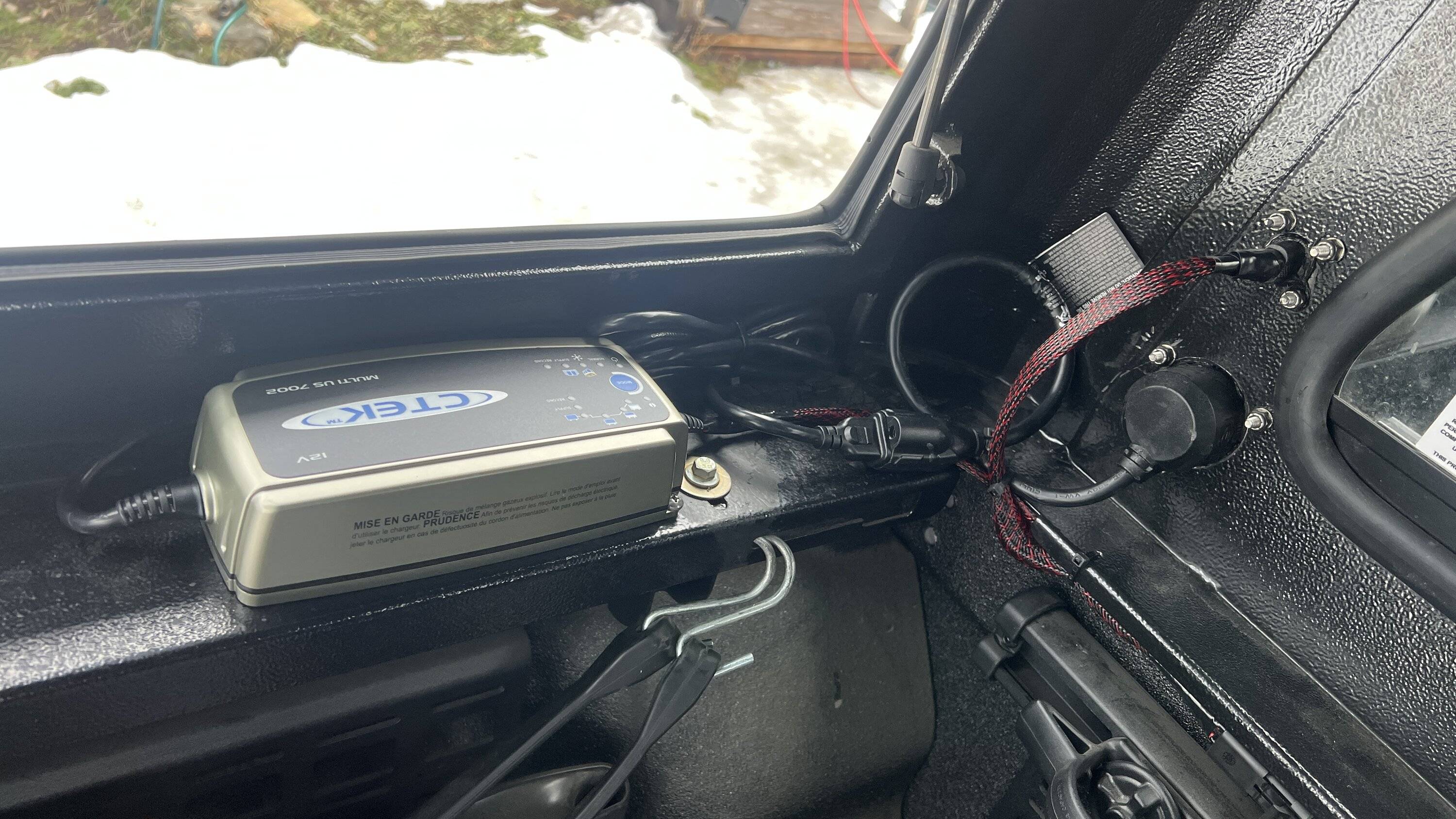
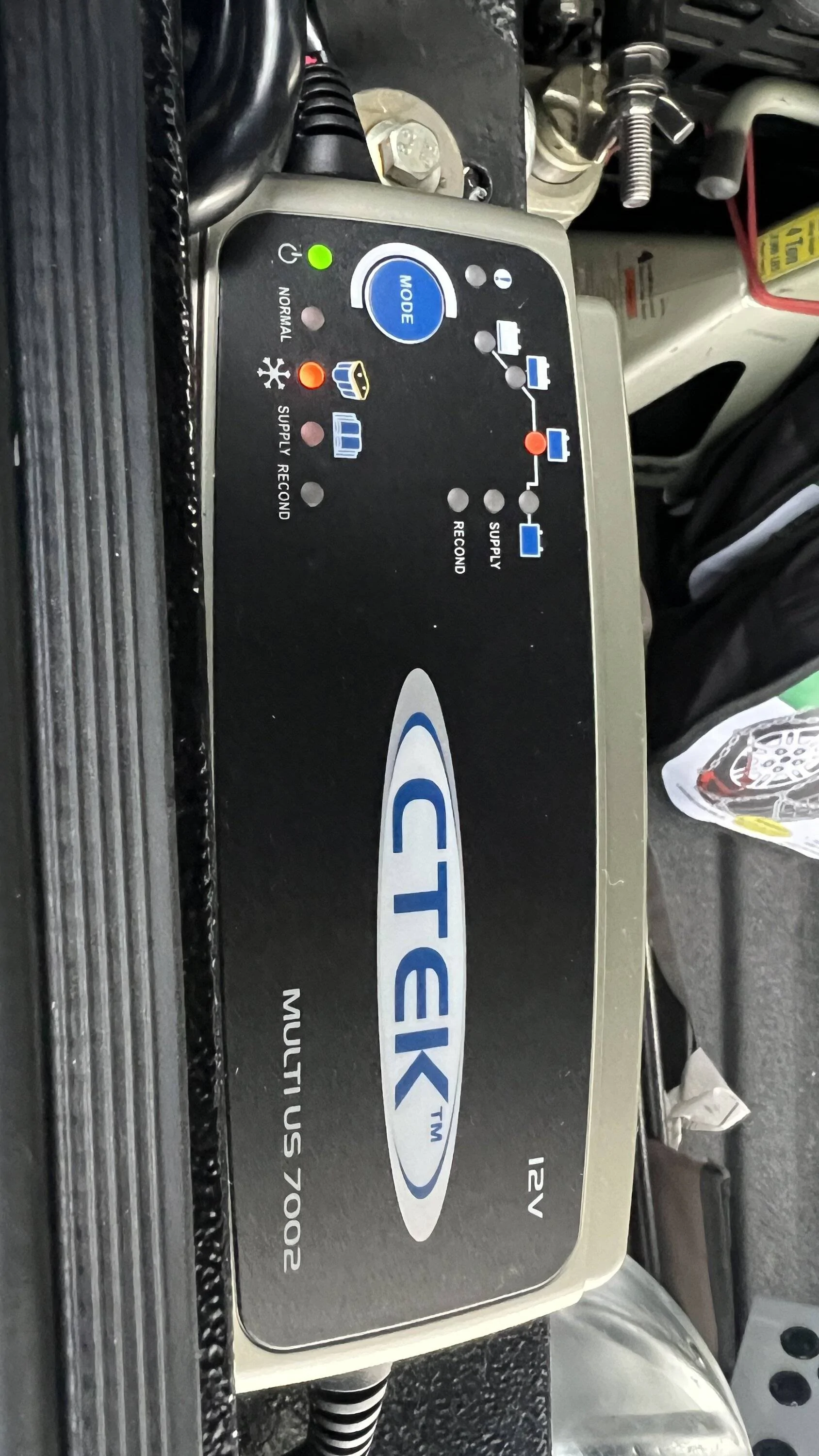
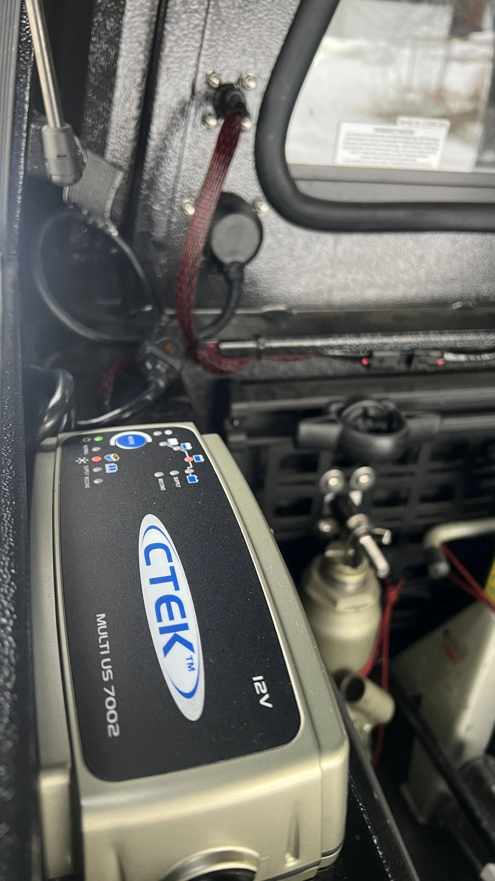
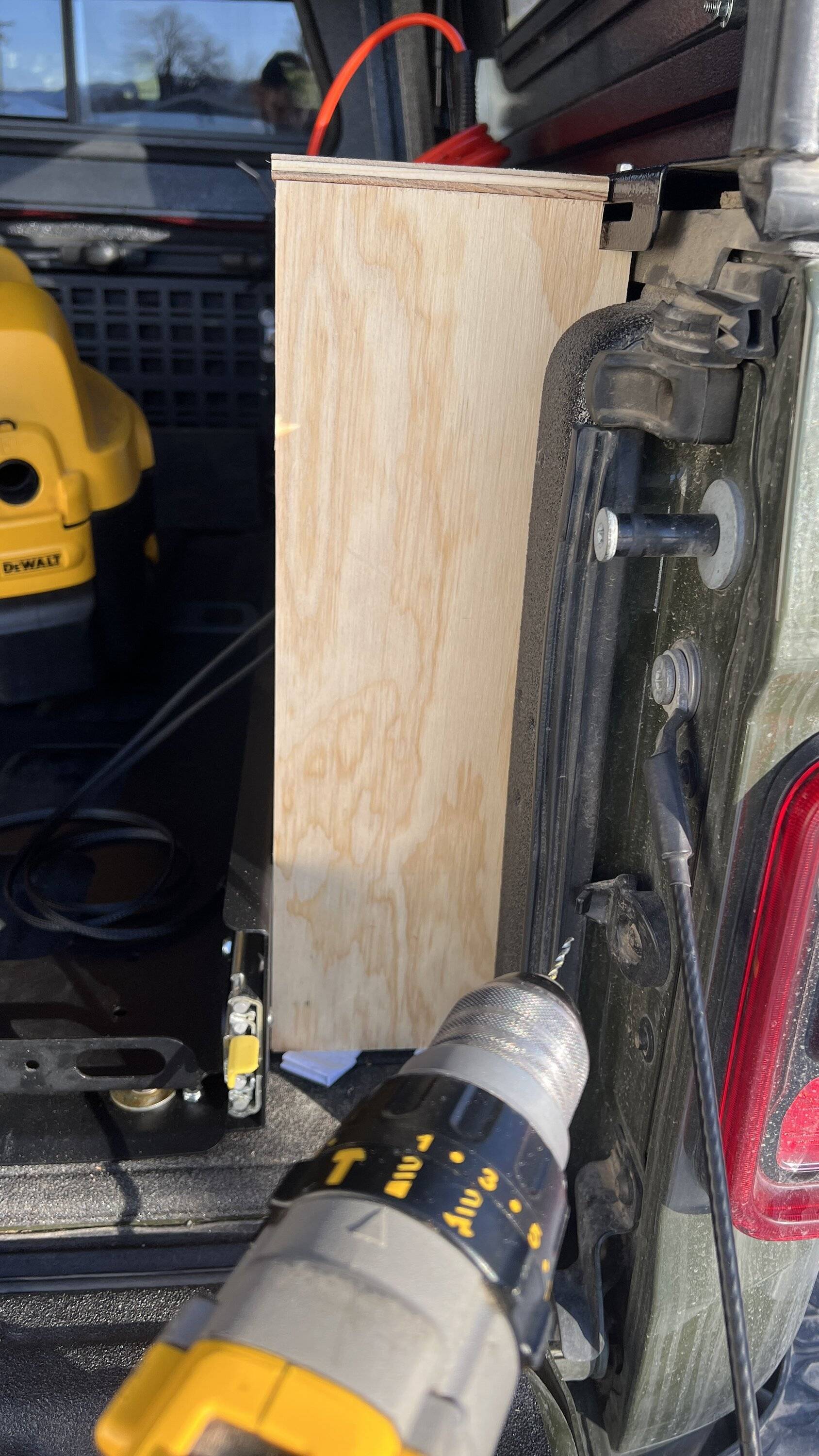
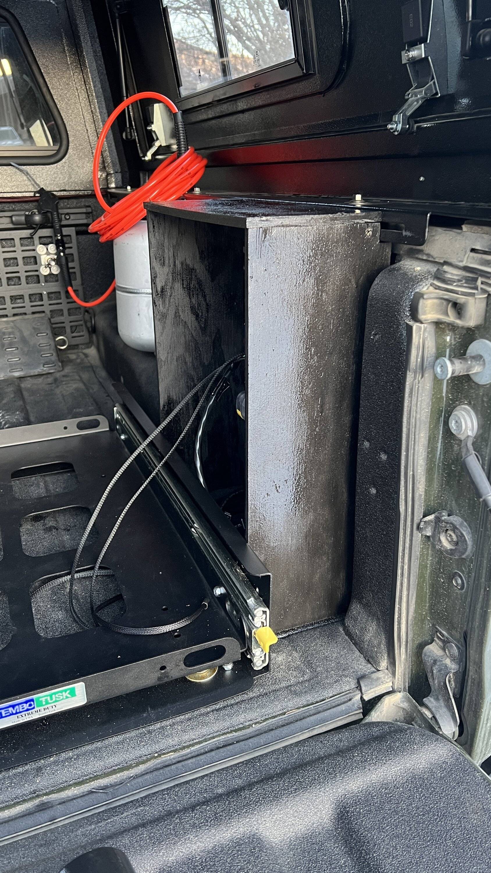
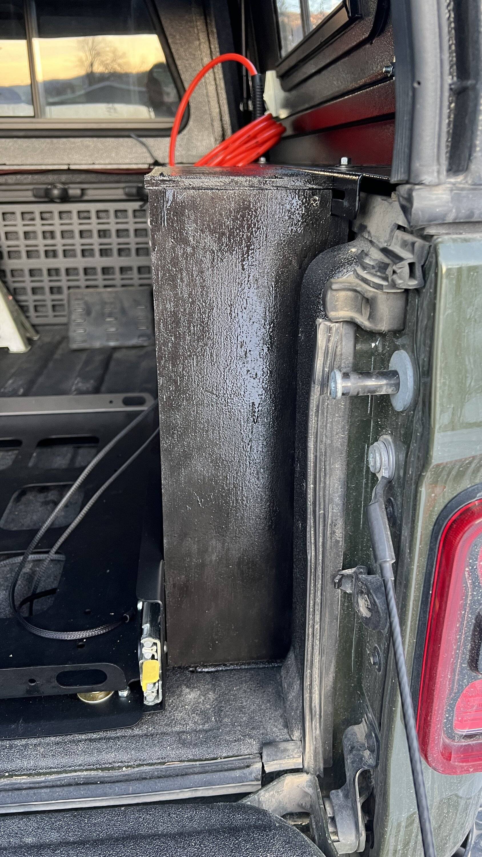
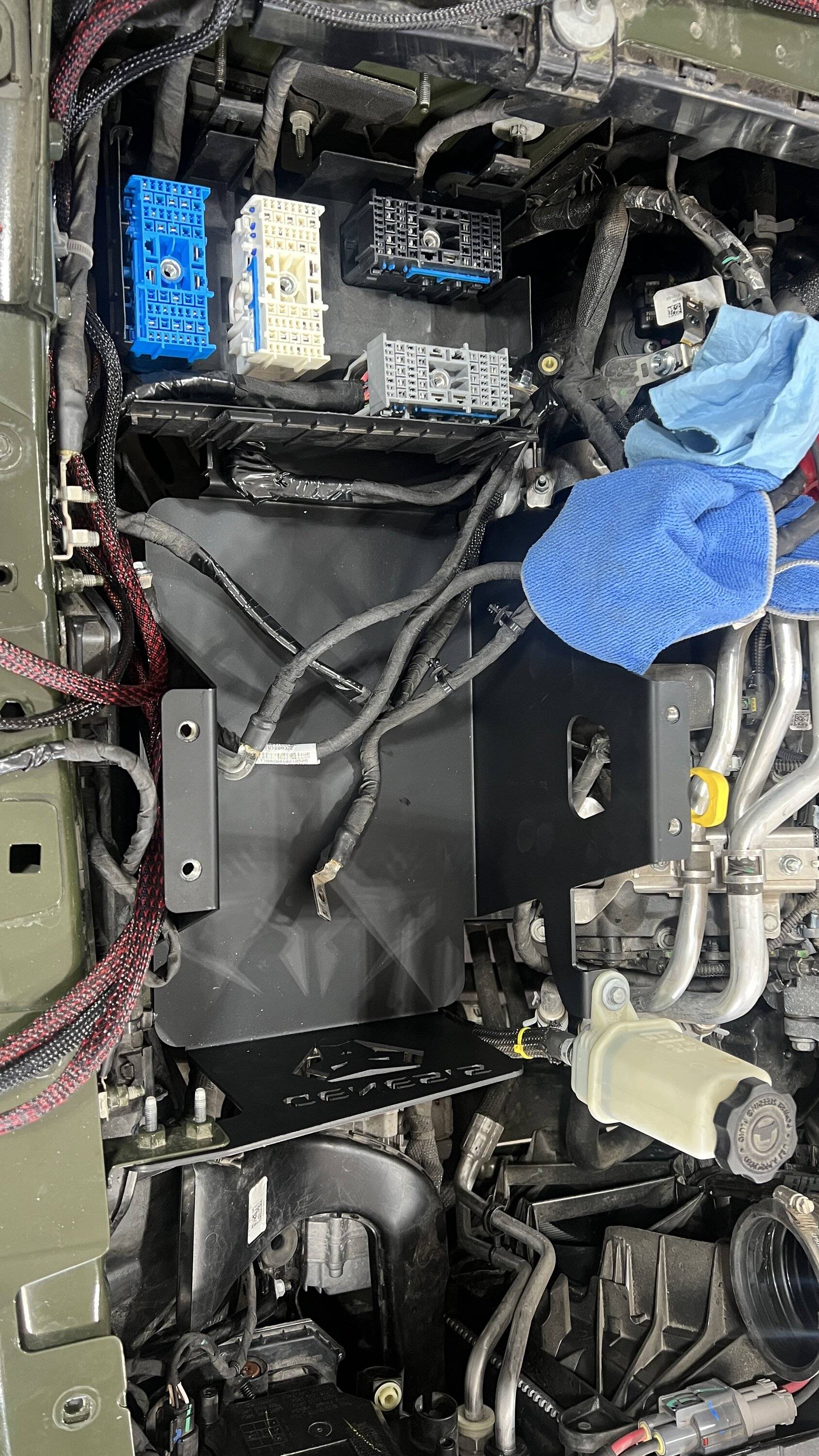
So the Genesis system at the moment is functioning. I do need to go back and clean up some wires and find a nice place to tuck the aux negative cable. Hopefully today I can finish getting the G screen installed and possibly wire up the battery charger/tender.
I must also give thanks to the folks on this forum who helped to resolve the issues by providing great info! Looking back - I could have done it a different way, and kept the factory group 31 size, and put an additional battery or two in the bed. That could arguably be a better way, and cheaper. But this is a sweet system with all the components included, and without a shop my fabrication options are limited and difficult to accomplish. I also like the G-screen option quite a lot, and having the lugs to attach my primary accessory distribution blocks to is cleaner than a bunch of wires on one single lug. Of course keeping all items taken off for every upgrade in the event I want to revert it back to stock form. Given I had a shop, all my tools, and better fabrication options than the current - I would have opted to keep the factory battery, deleted the aux, and fabricated my own system to go in the bed
After some work this morning I will check to see what battery voltages are for curiosity since it is cold, finish cleaning up some wiring, and begin G-screen install and hopefully battery tender as well.

Sponsored