Sponsored
OP
OP
chorky

chorky

Well-Known Member
First Name
Chad
Joined
Feb 26, 2022
Threads
175
Messages
3,466
Reaction score
3,801
Location
Montana
Website
www.youtube.com
Vehicle(s)
'22JTR, '06 LJ, '06 TJ GE
Build Thread
Link
Occupation
GIS Specialist
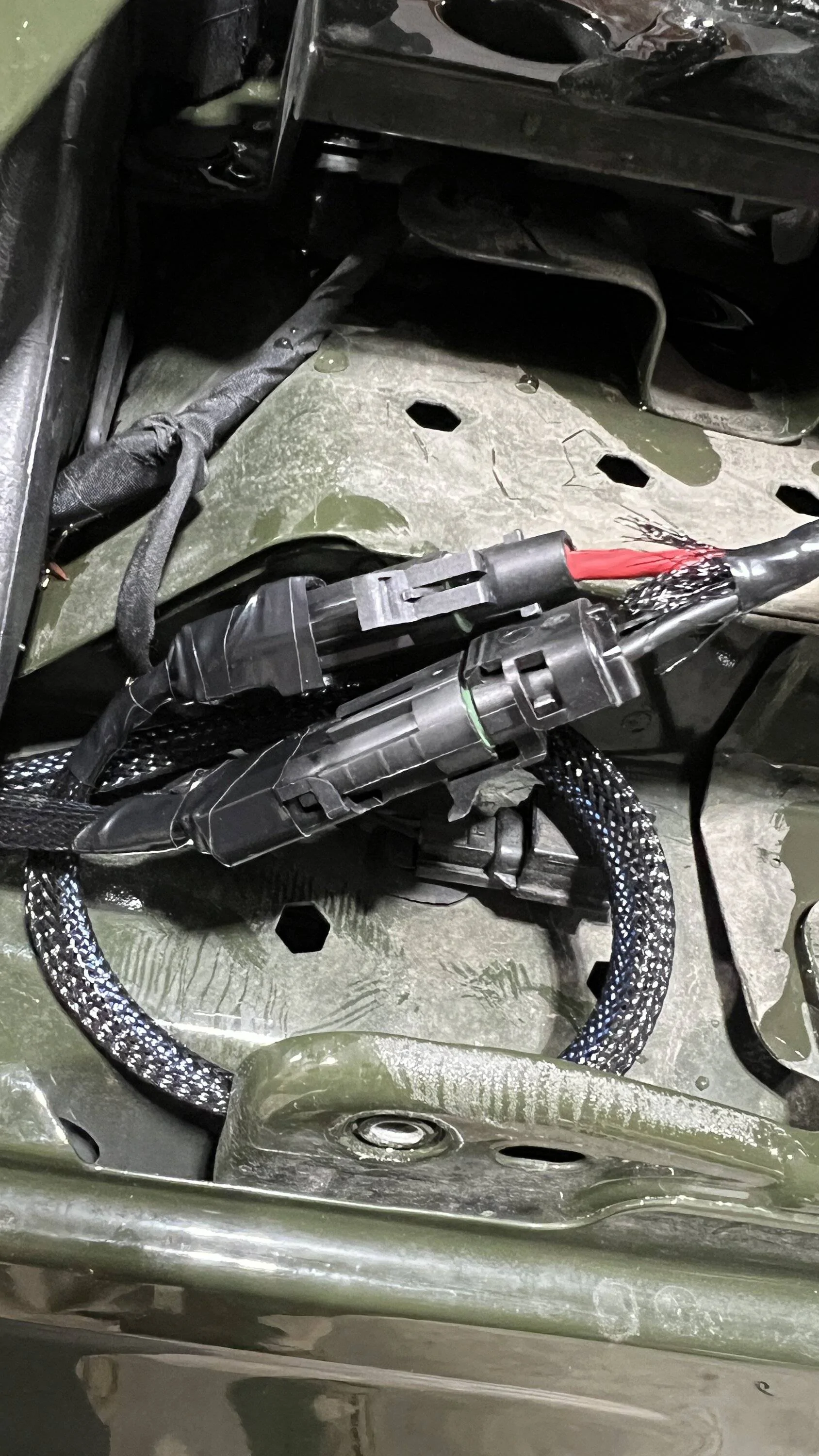
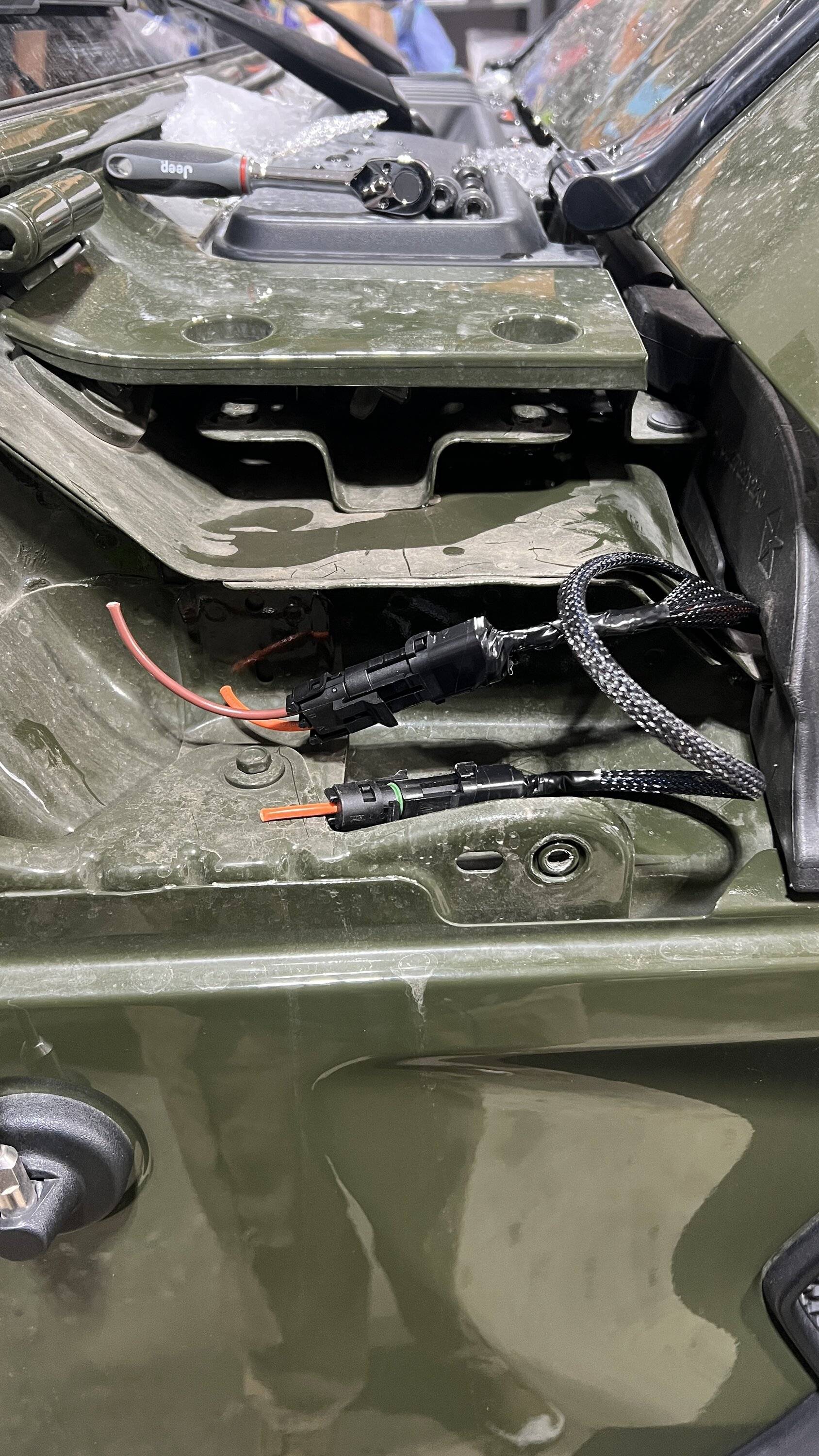
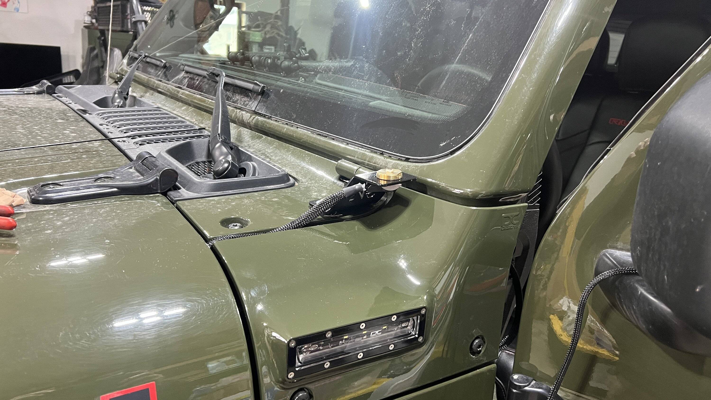
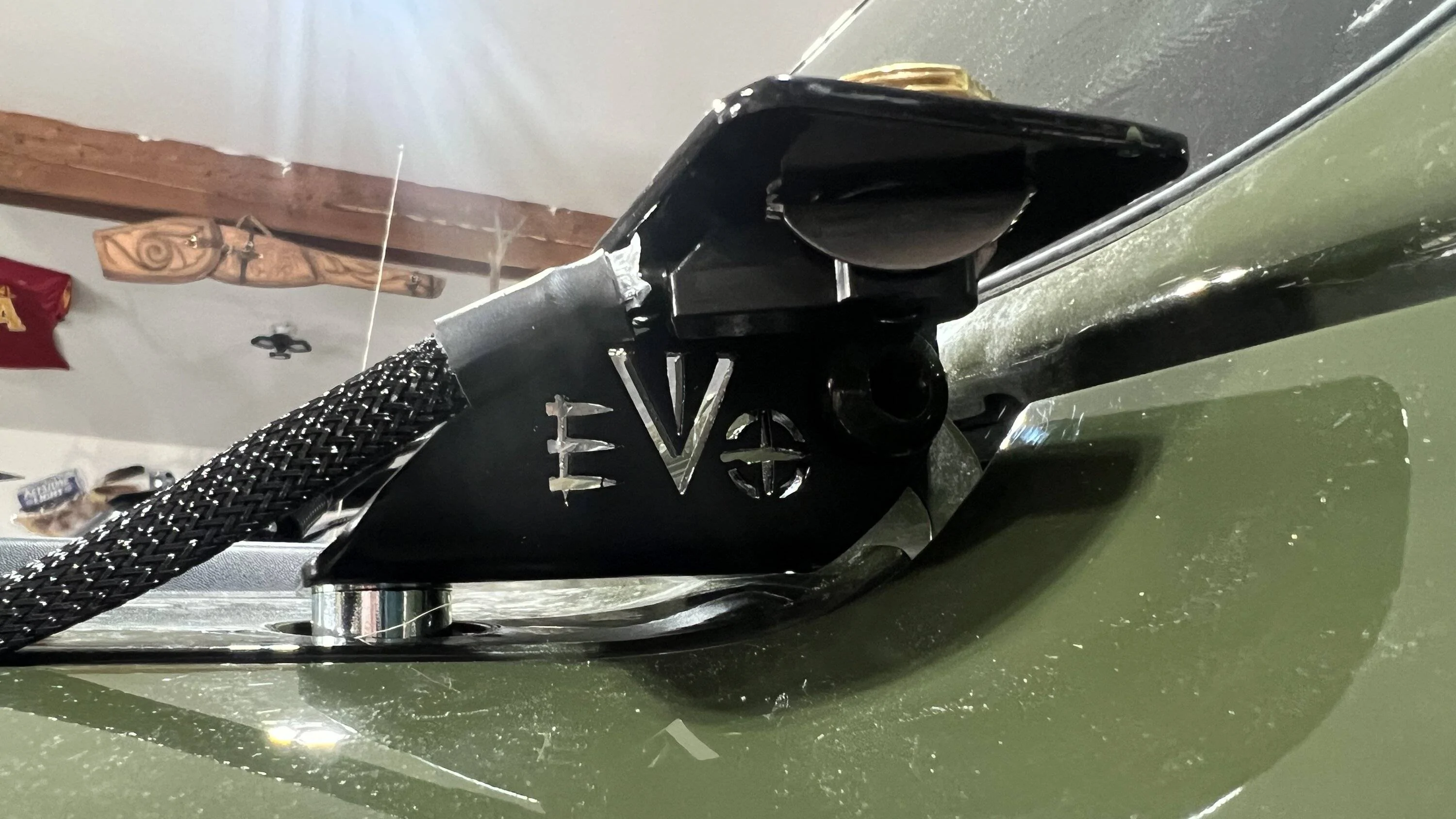
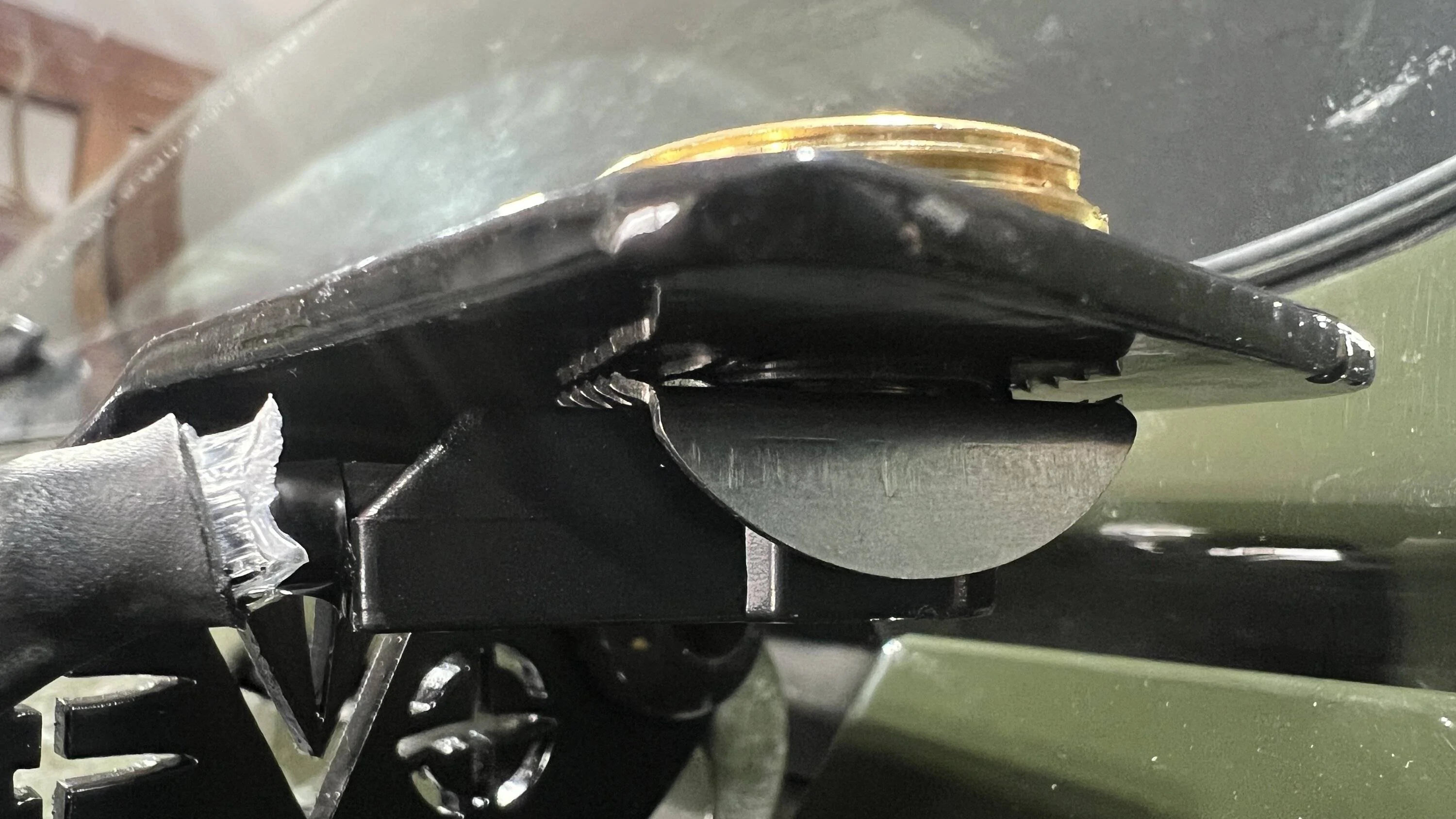
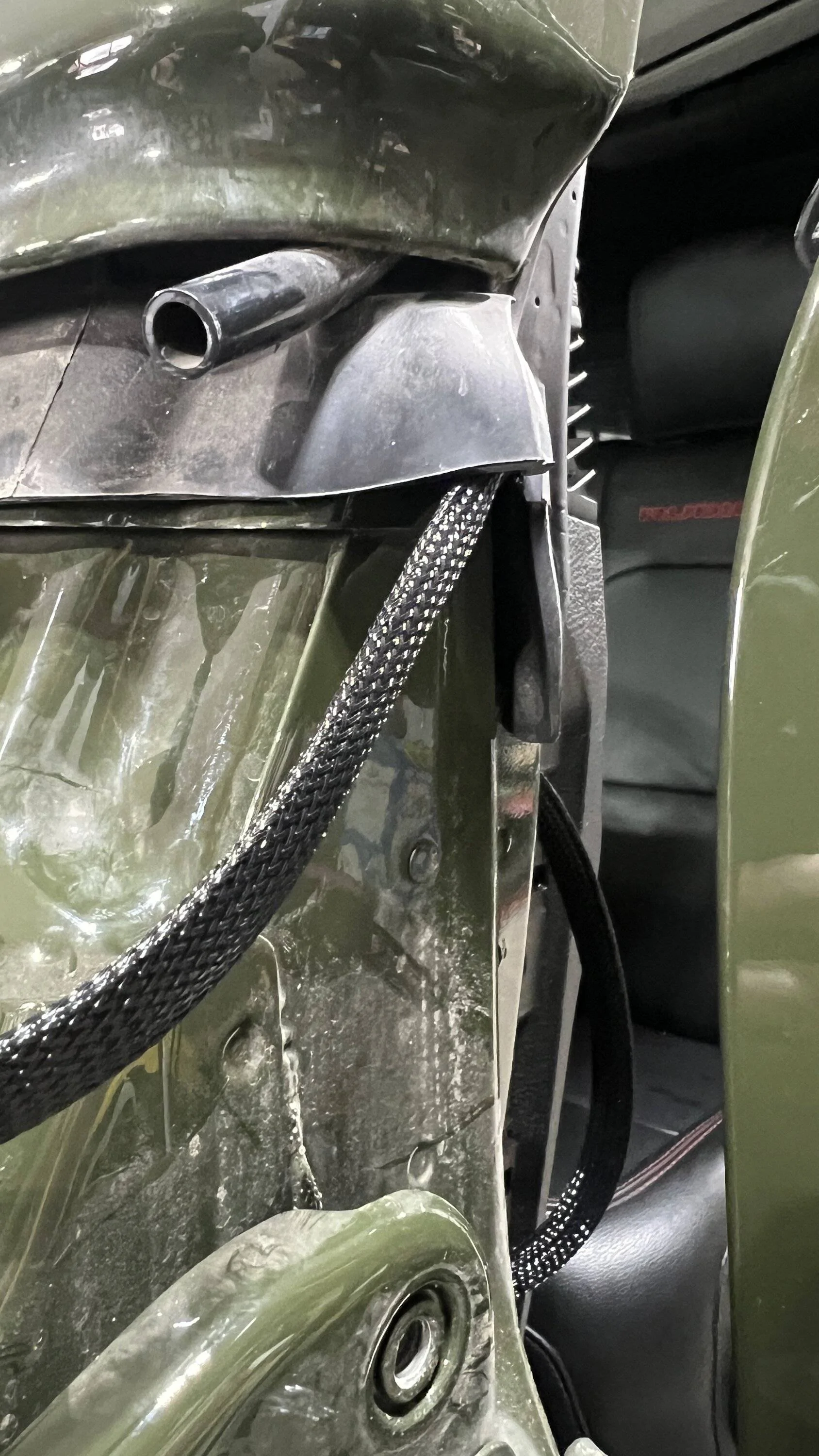
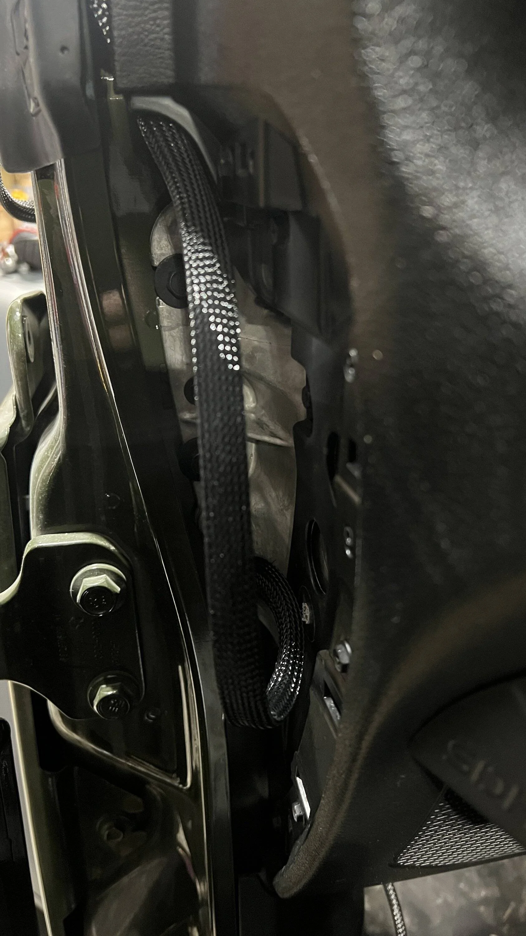
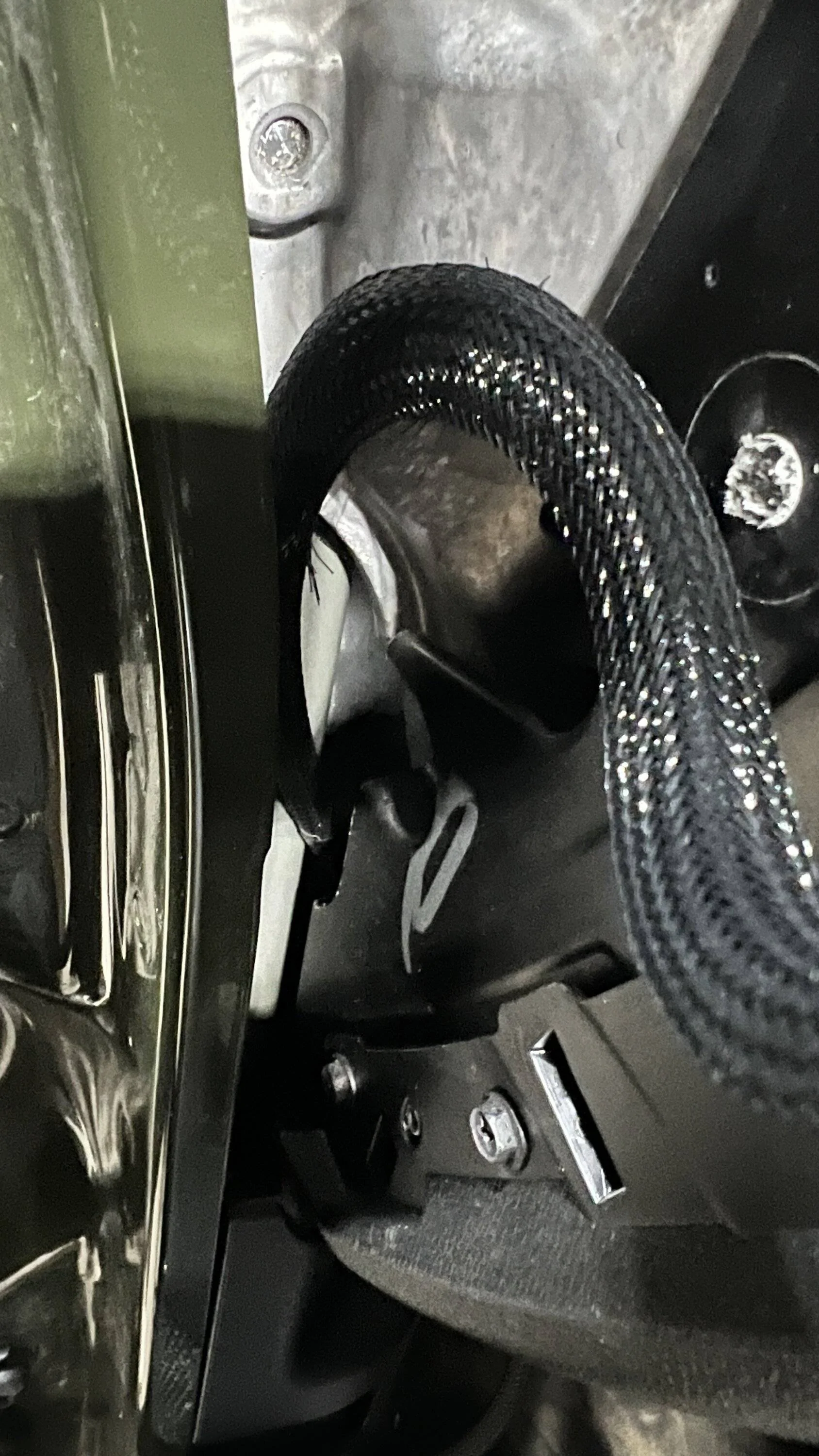
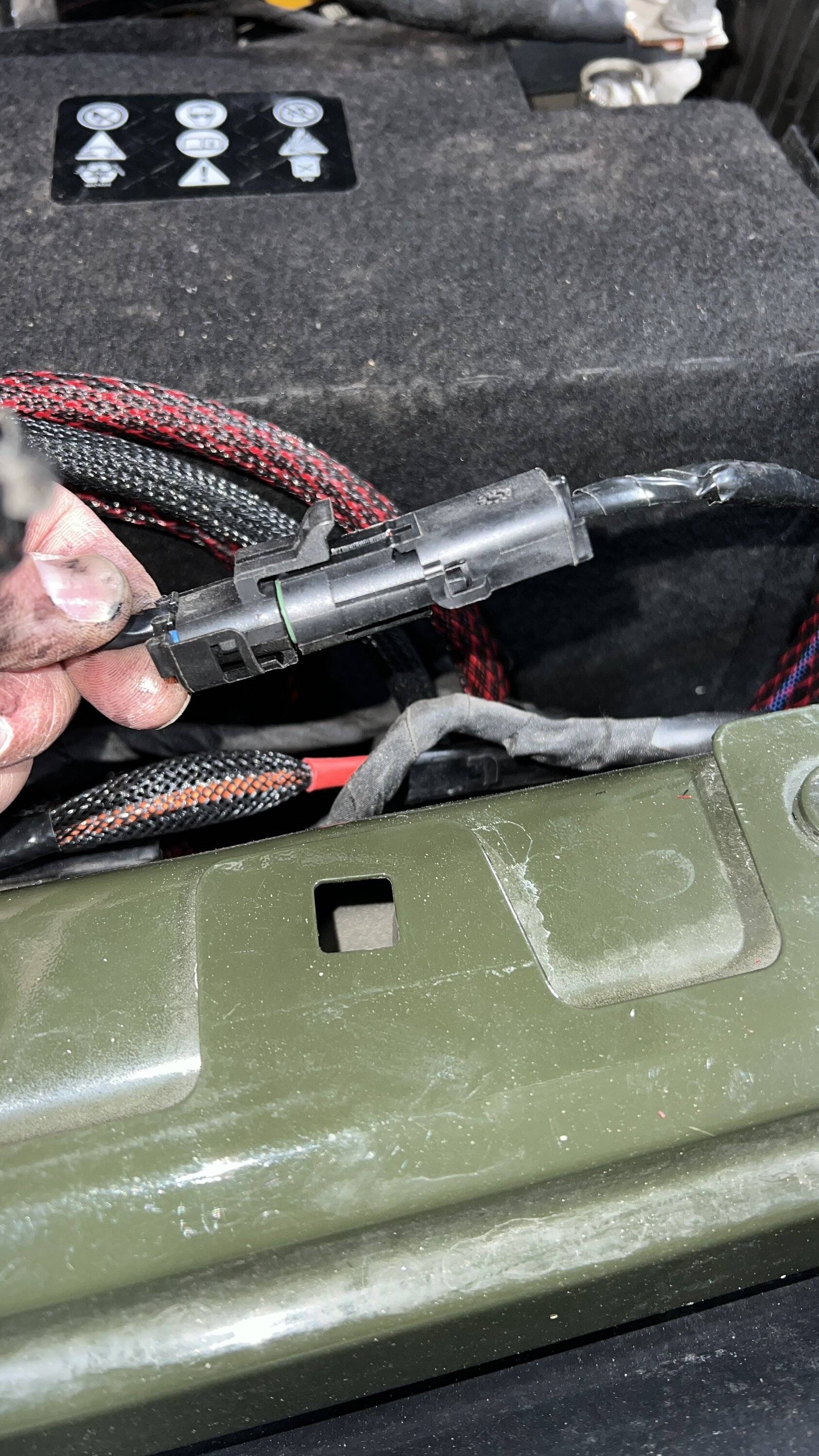
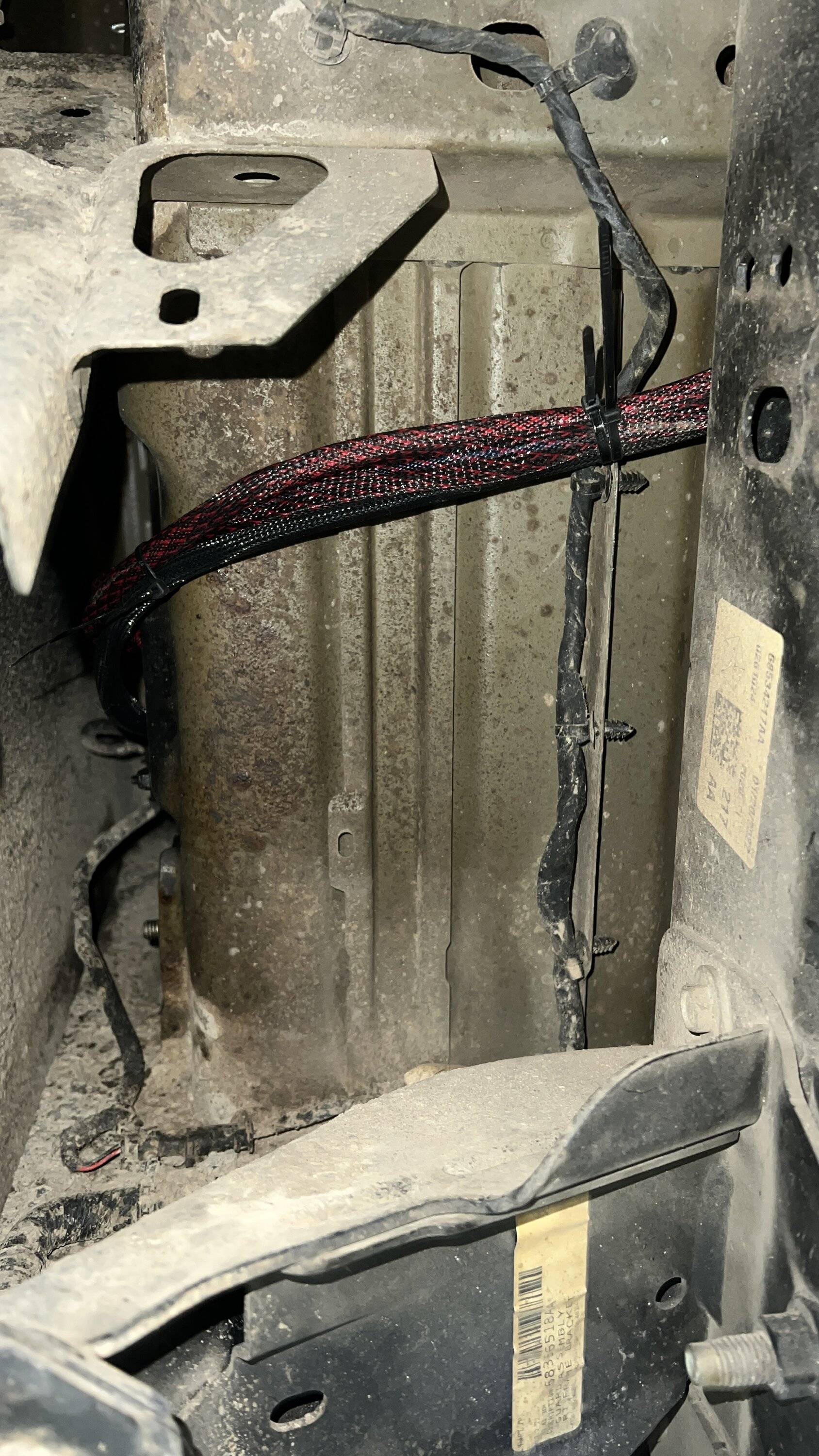
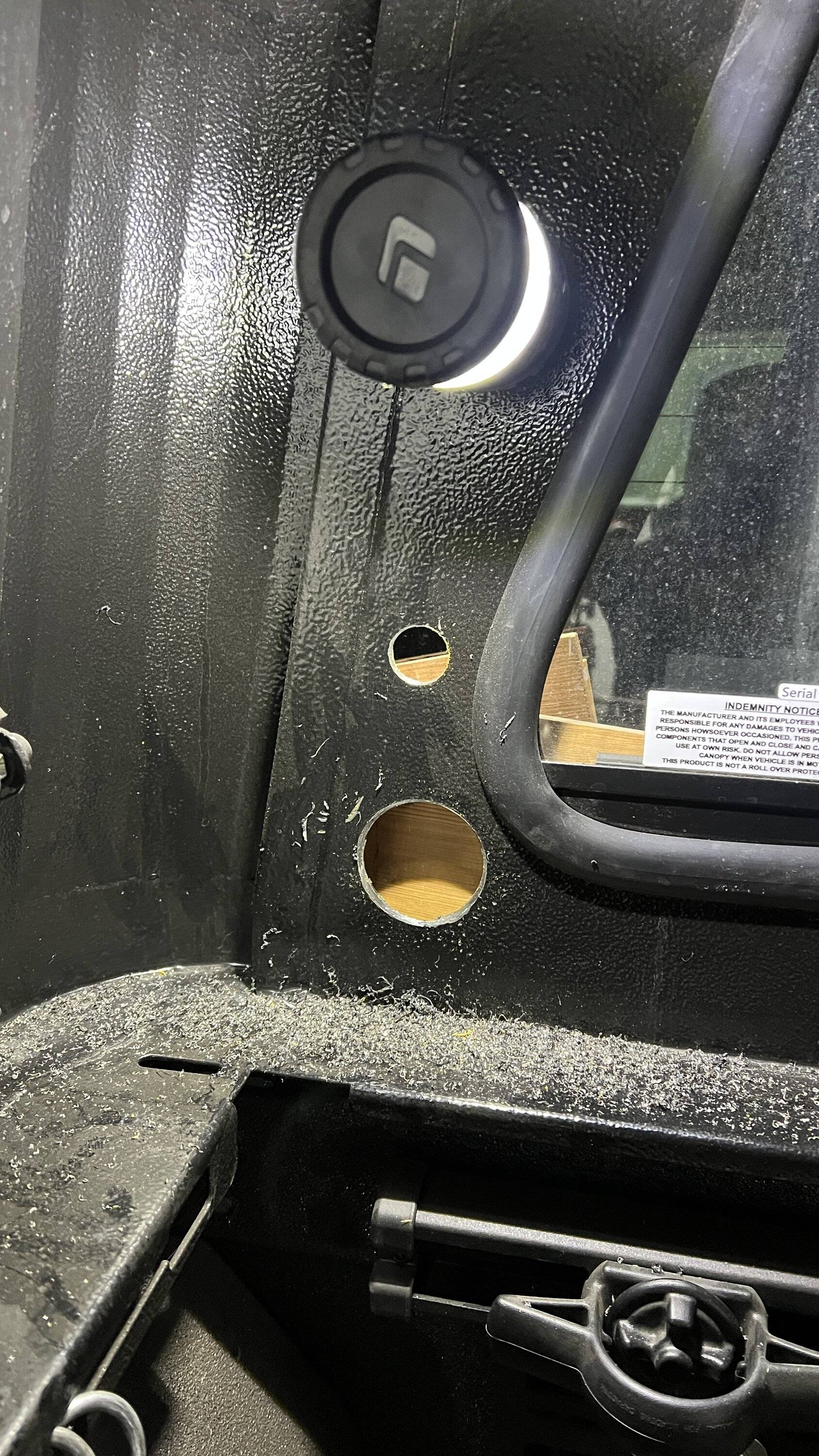
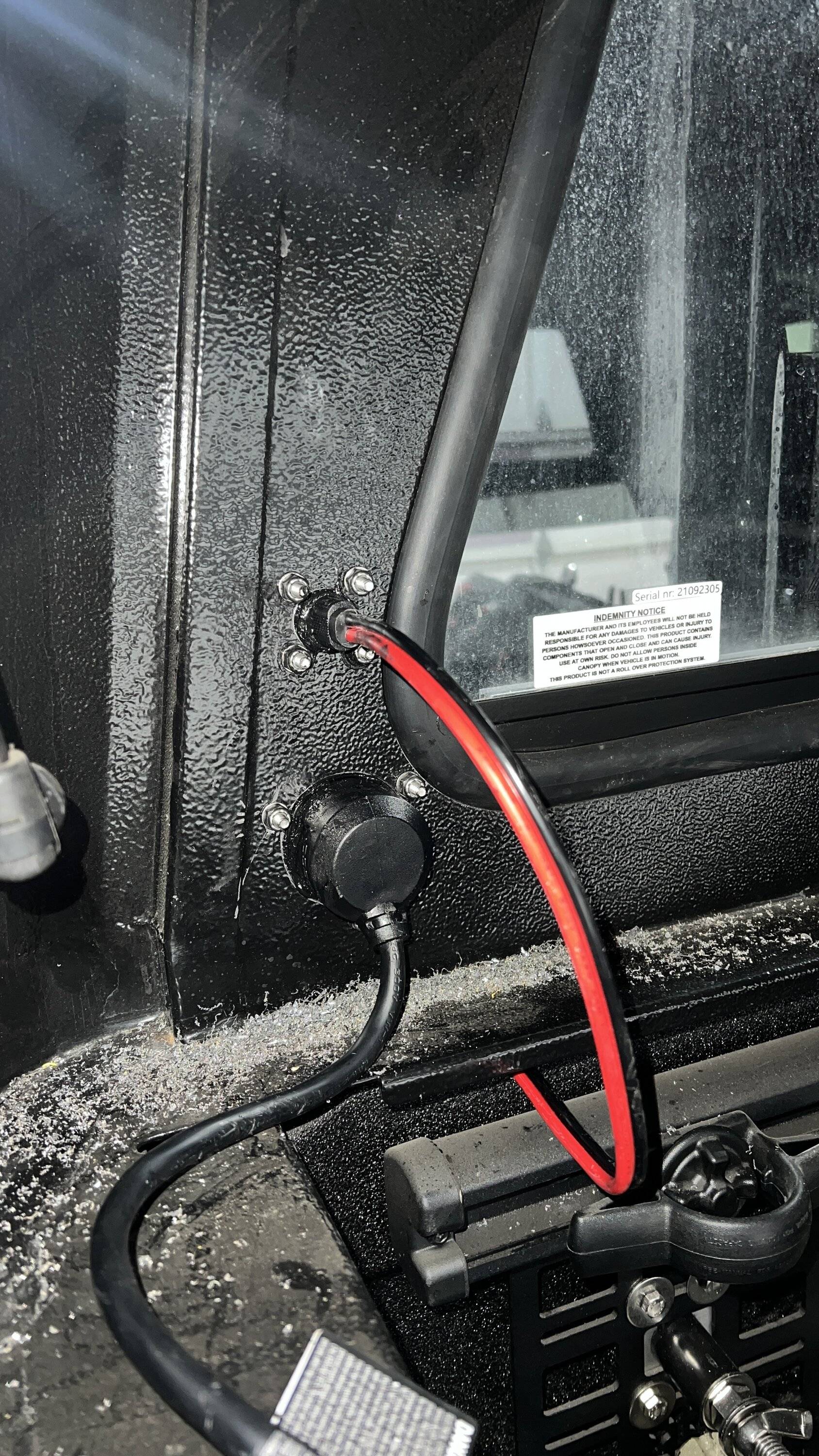
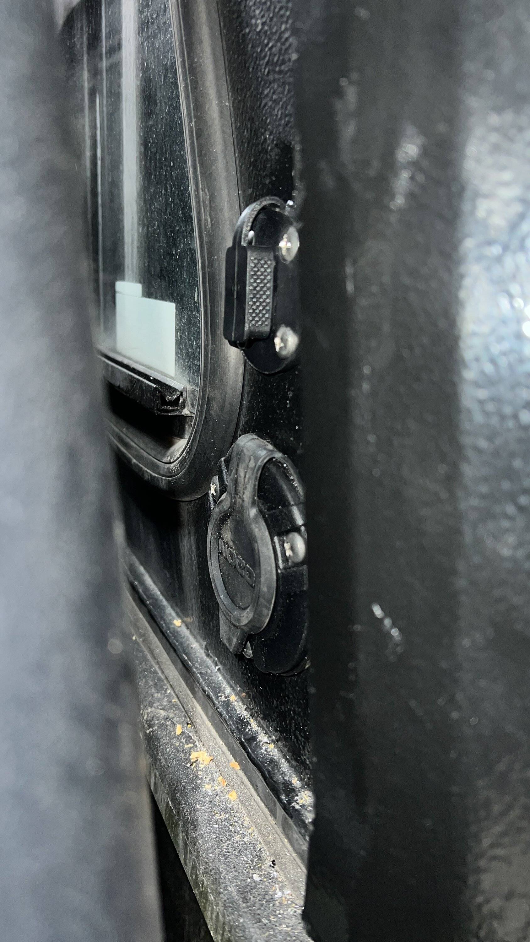
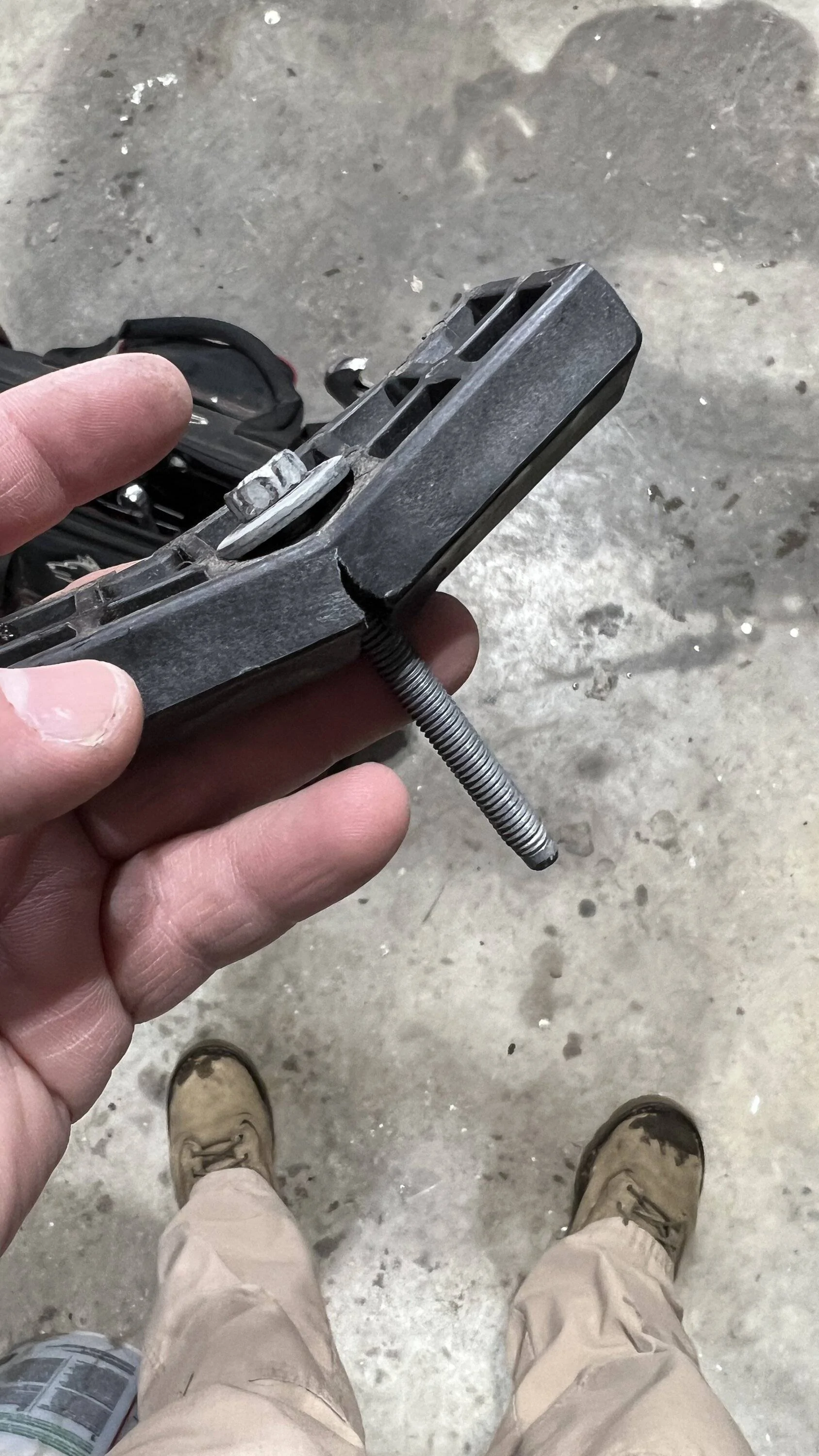
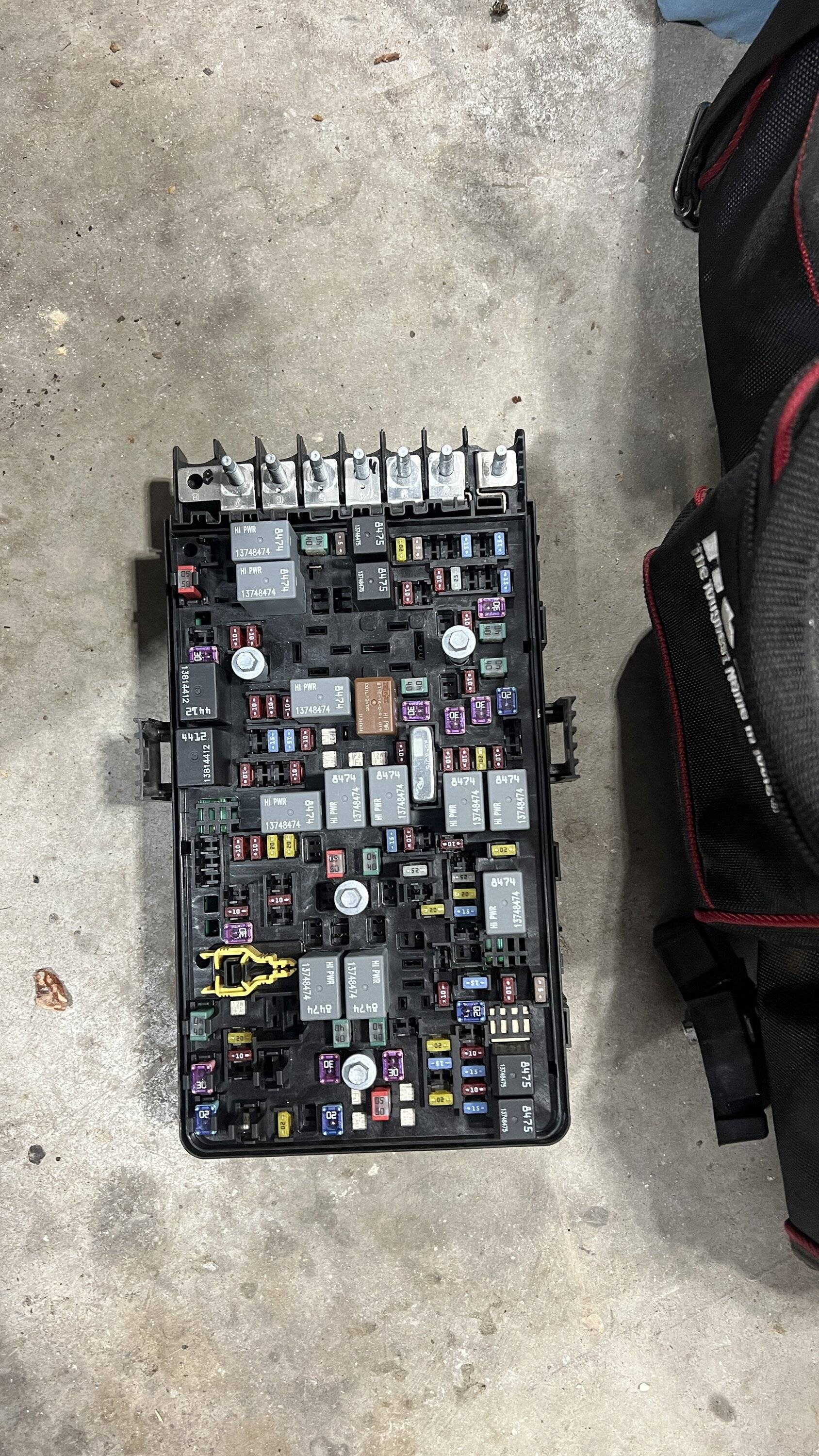
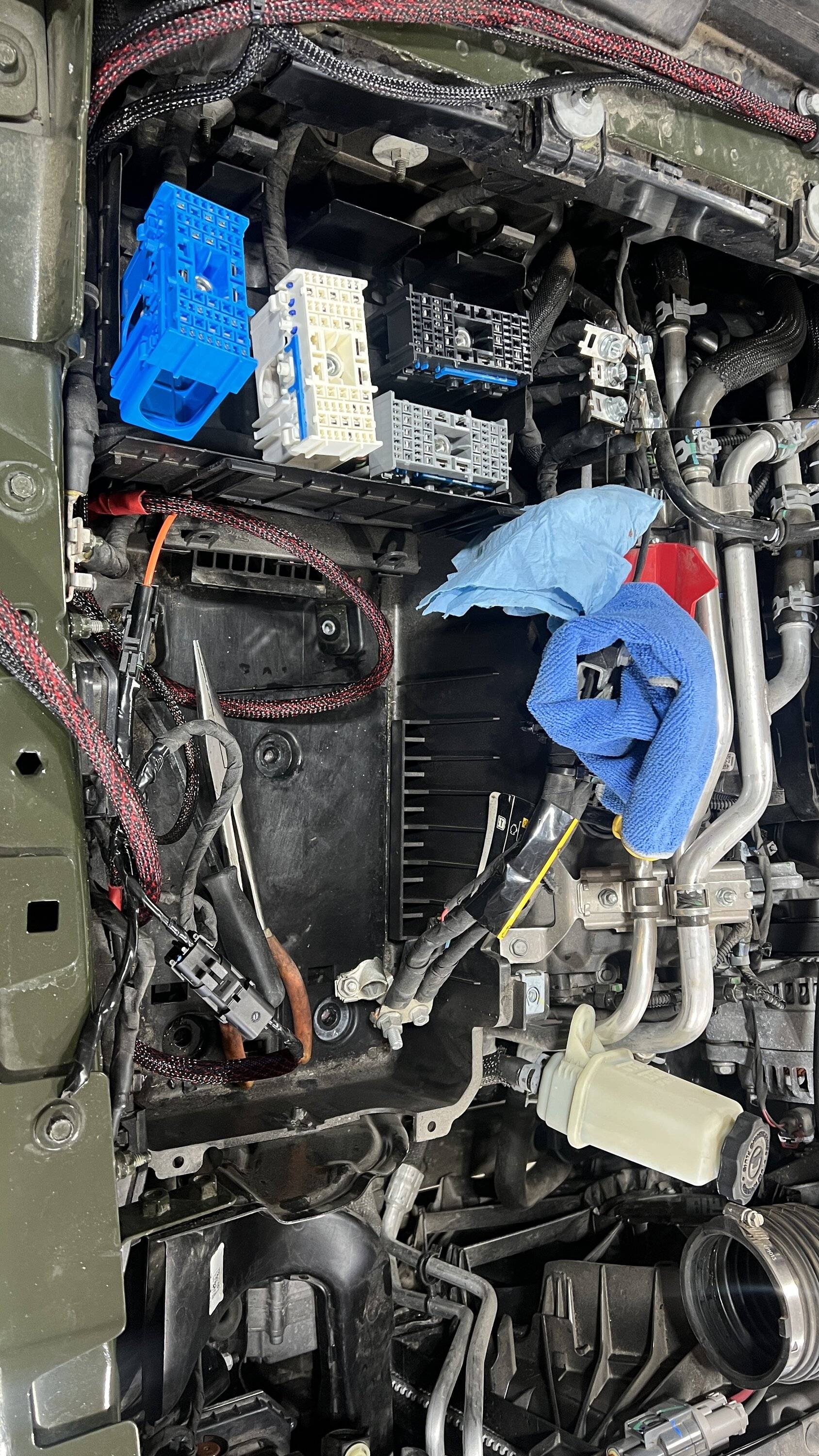
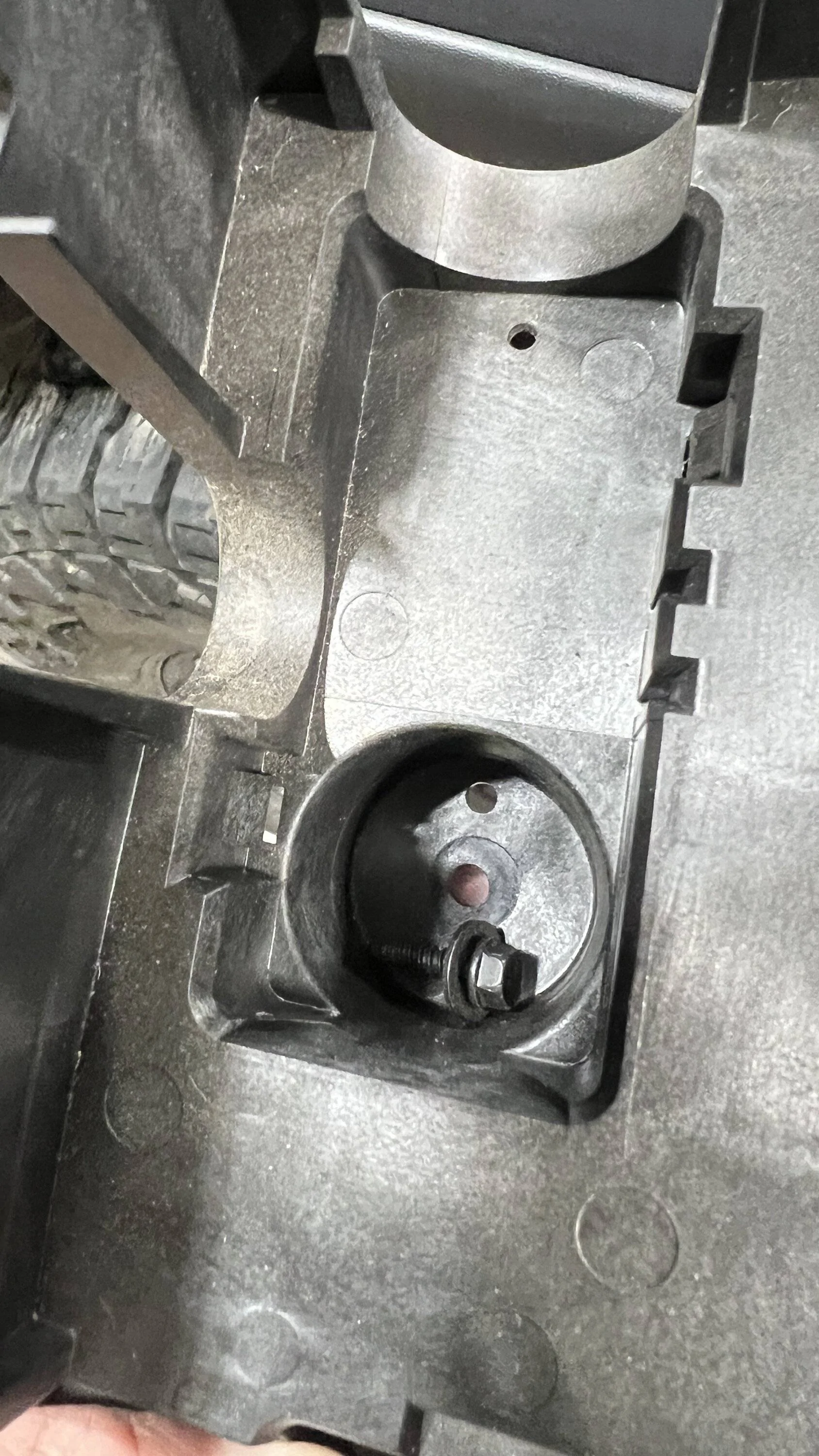
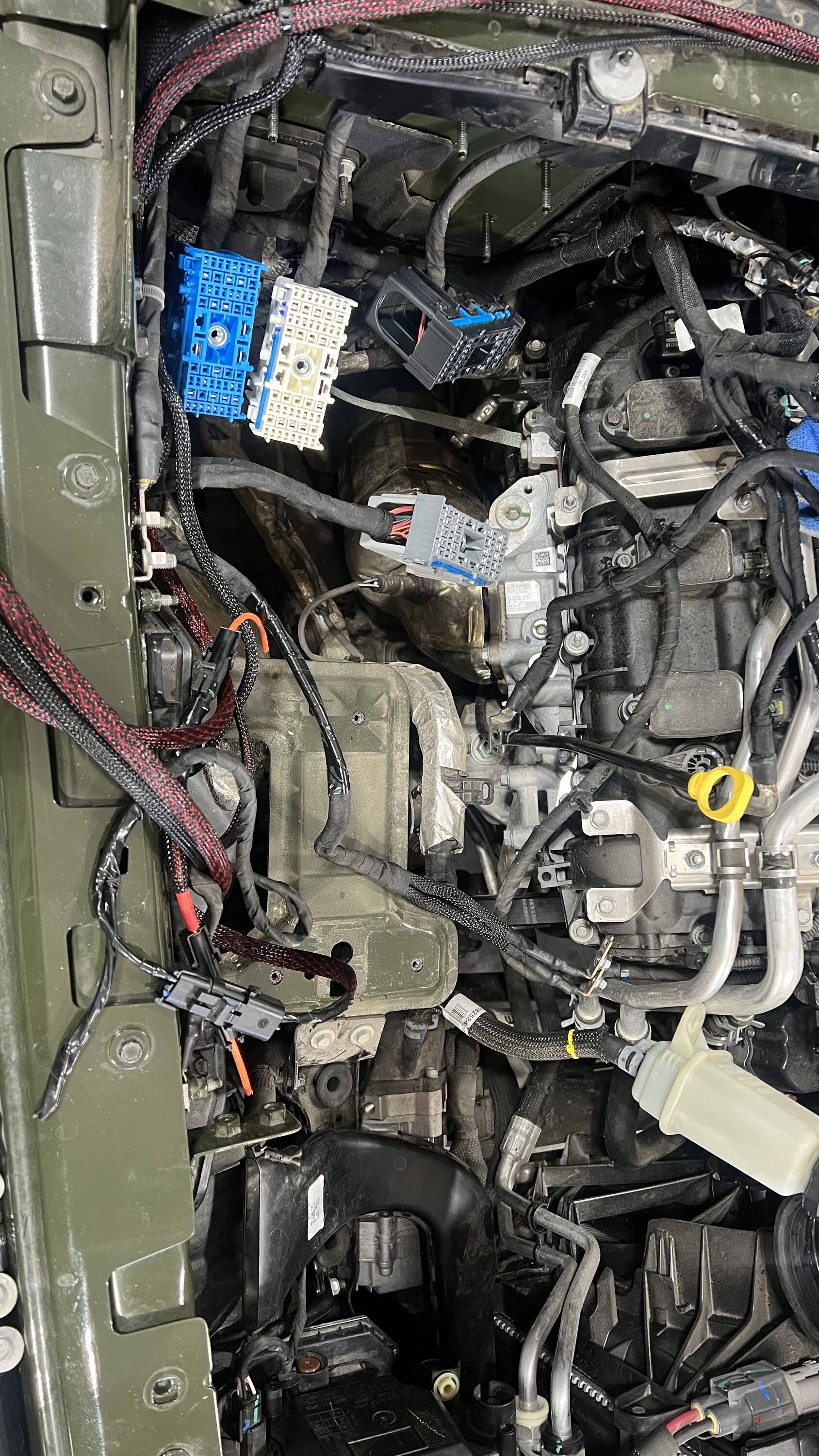
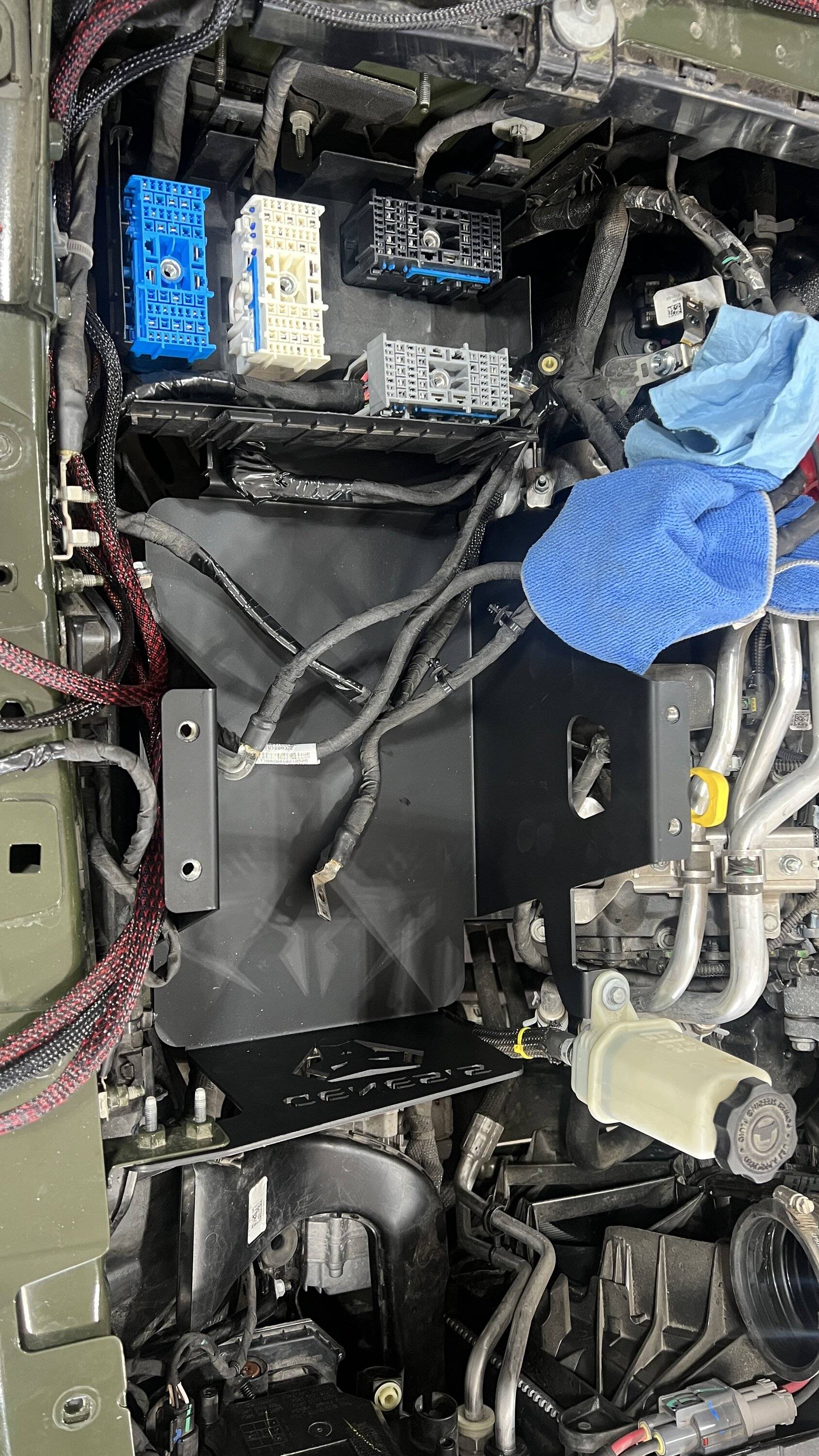
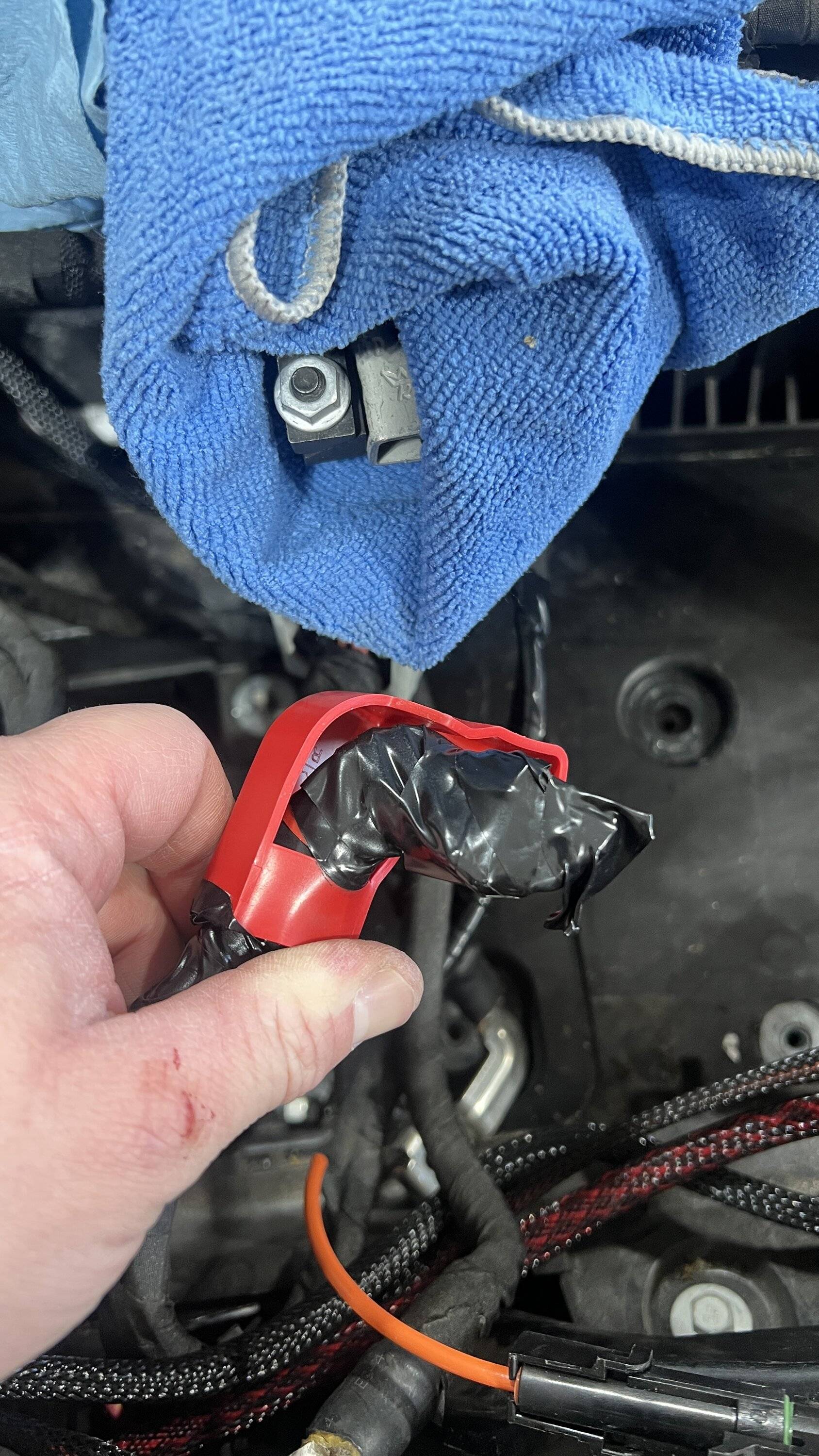
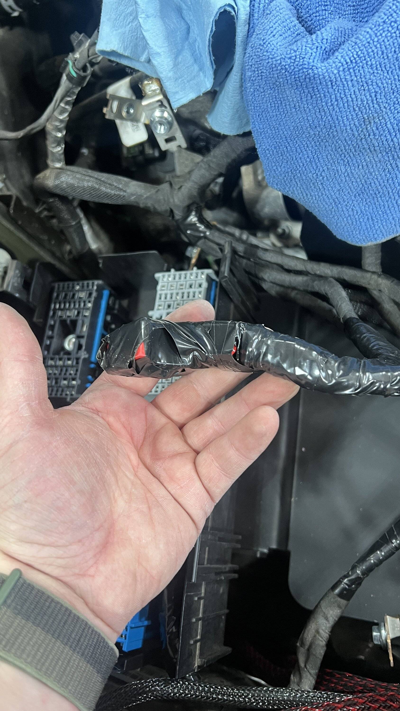
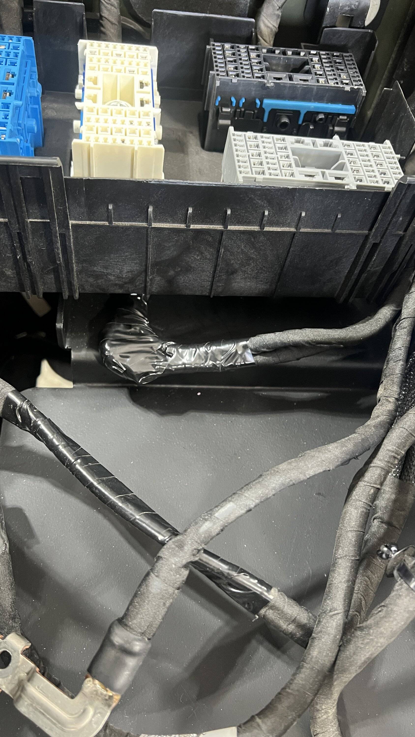
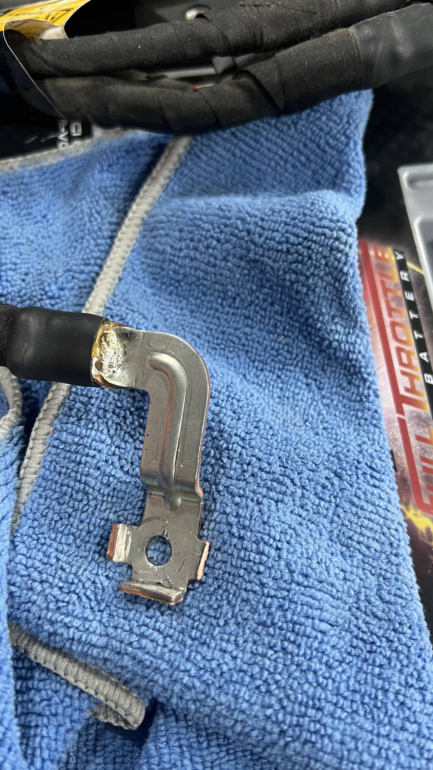
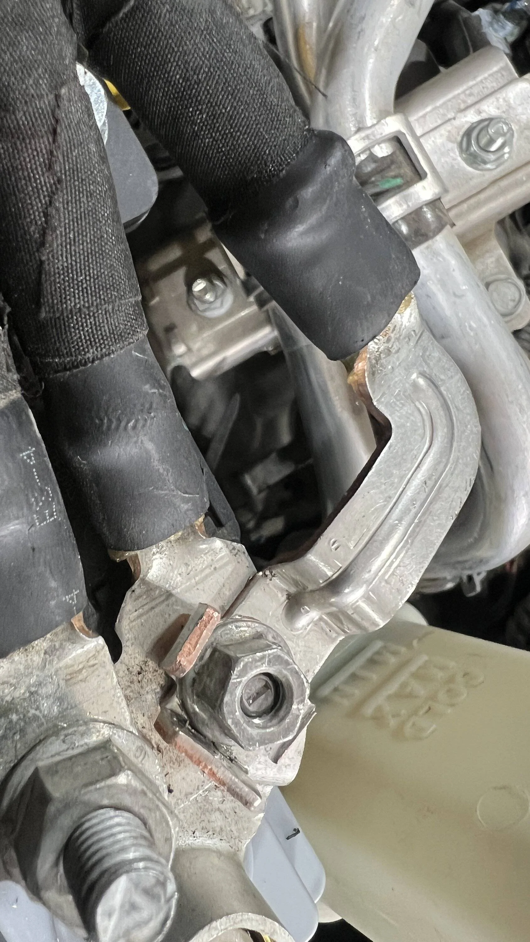
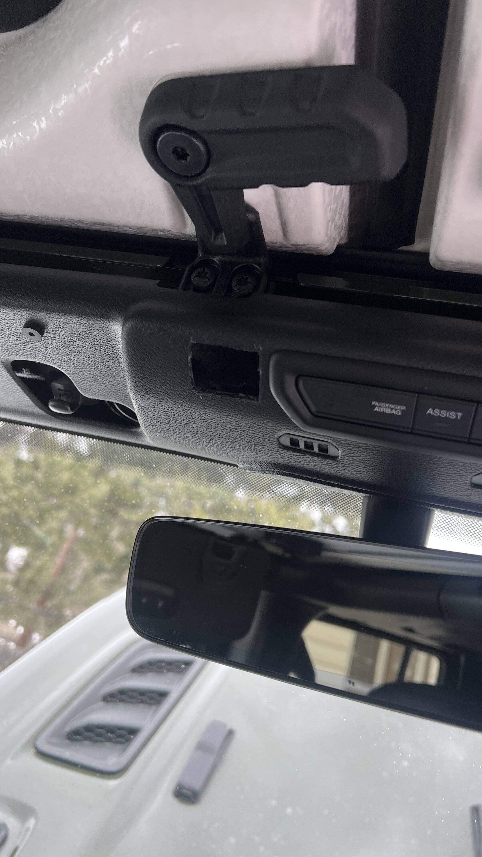
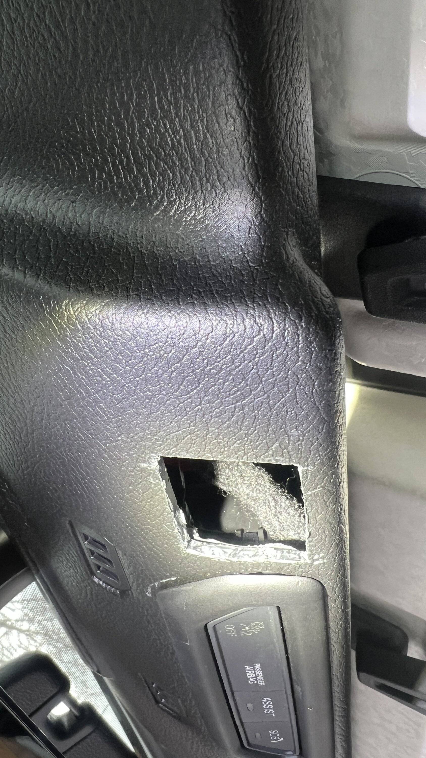
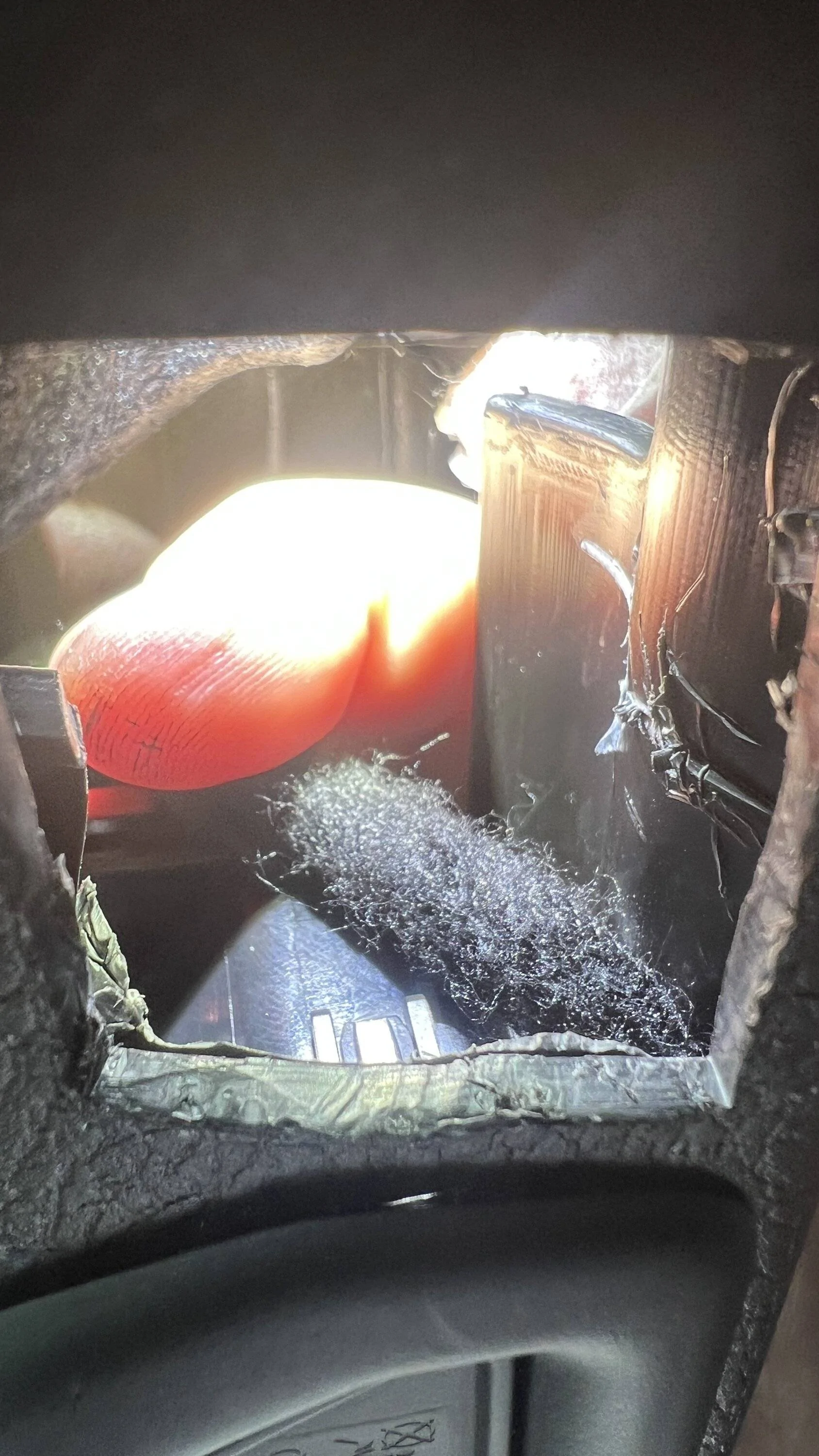
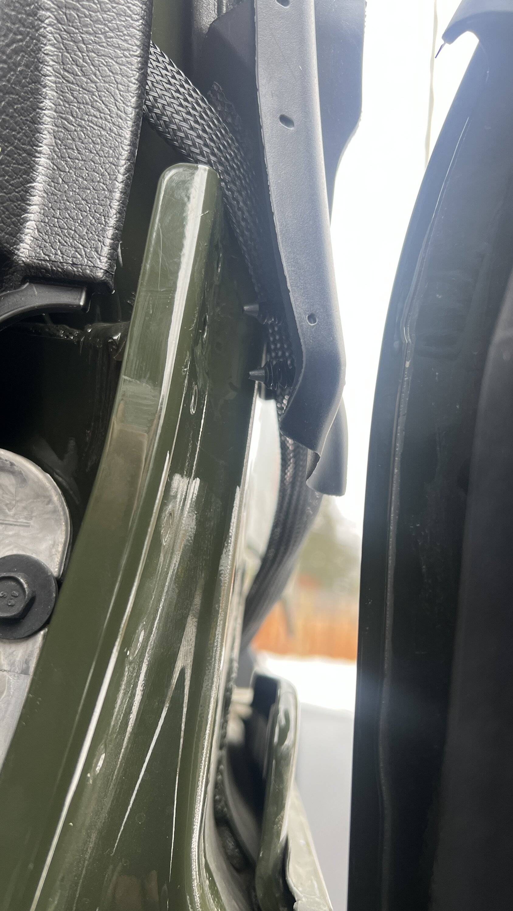
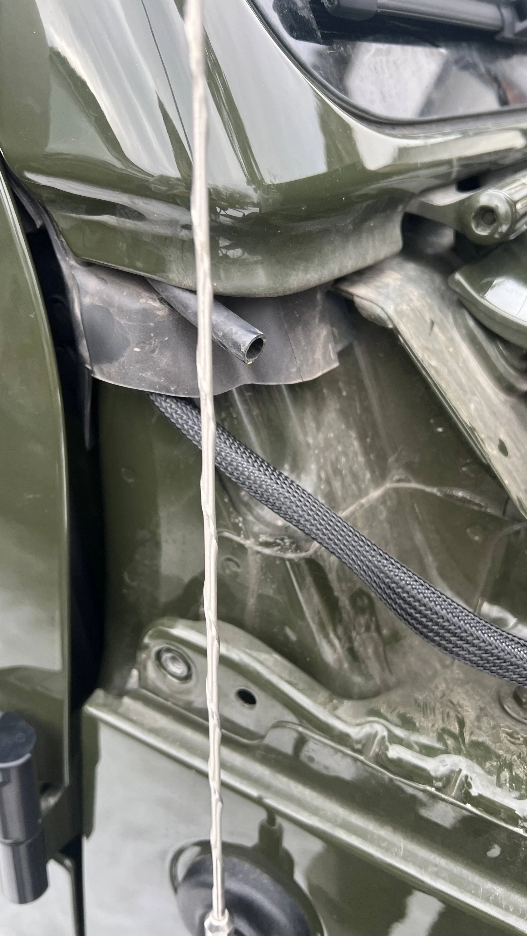
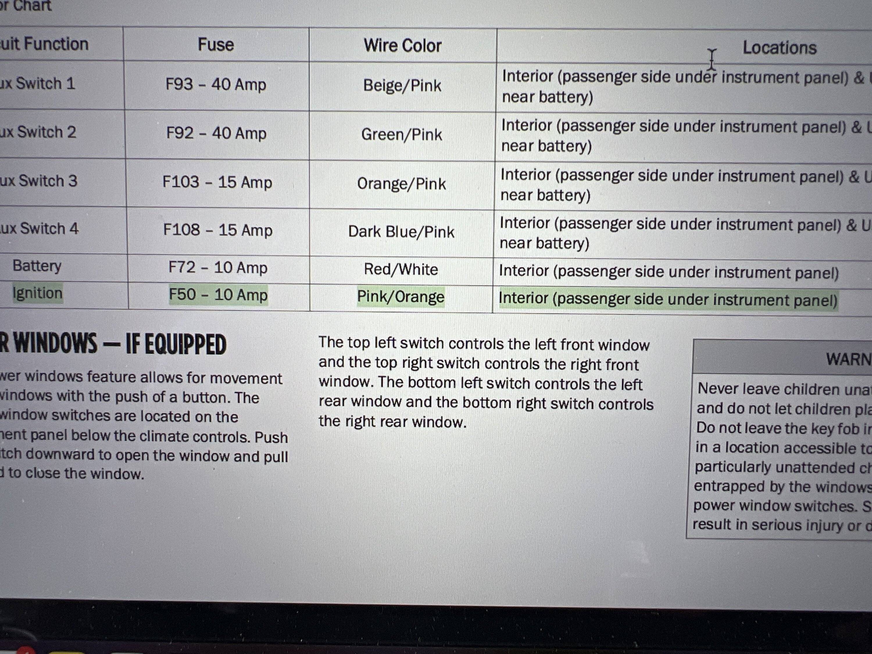
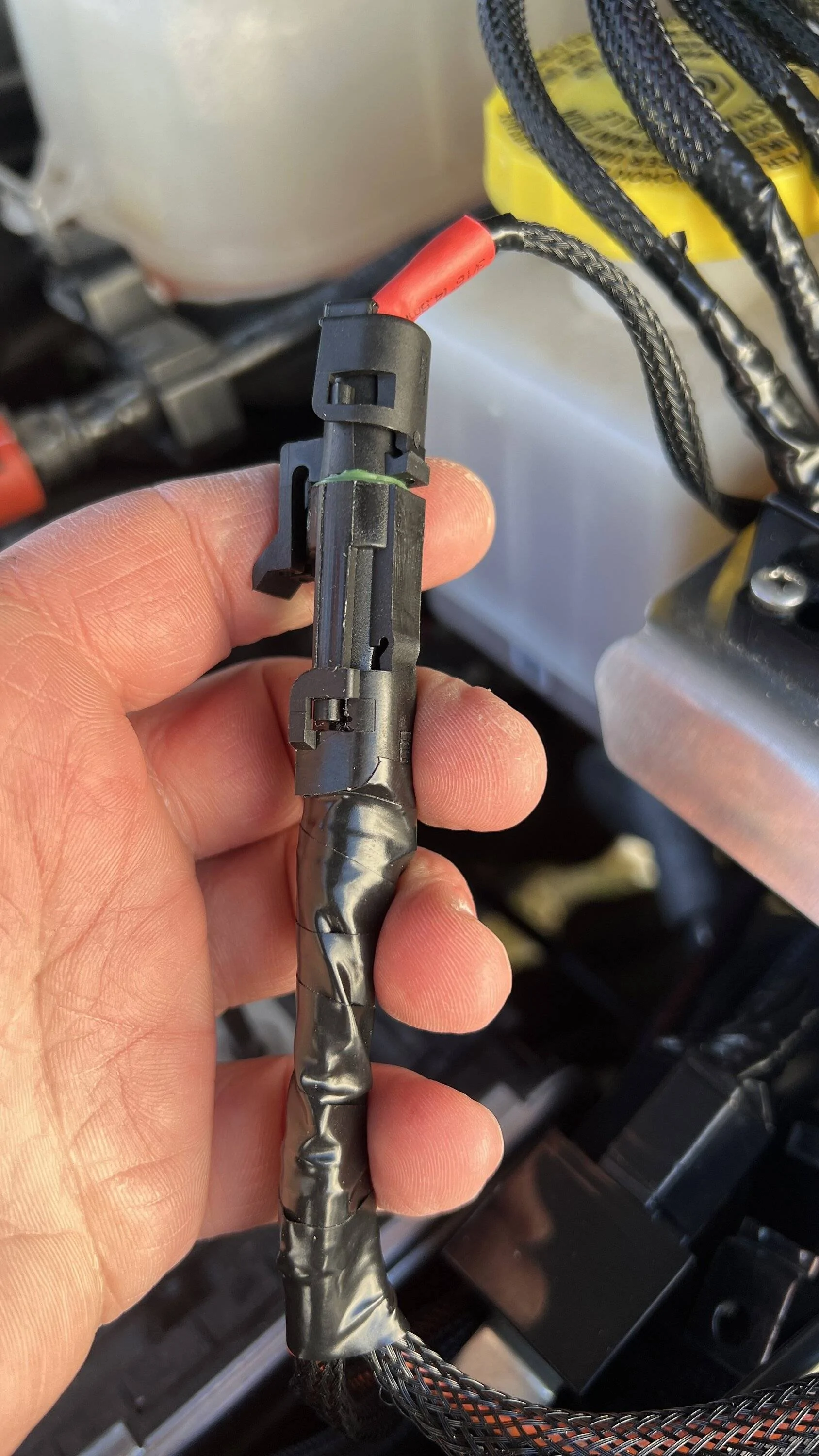
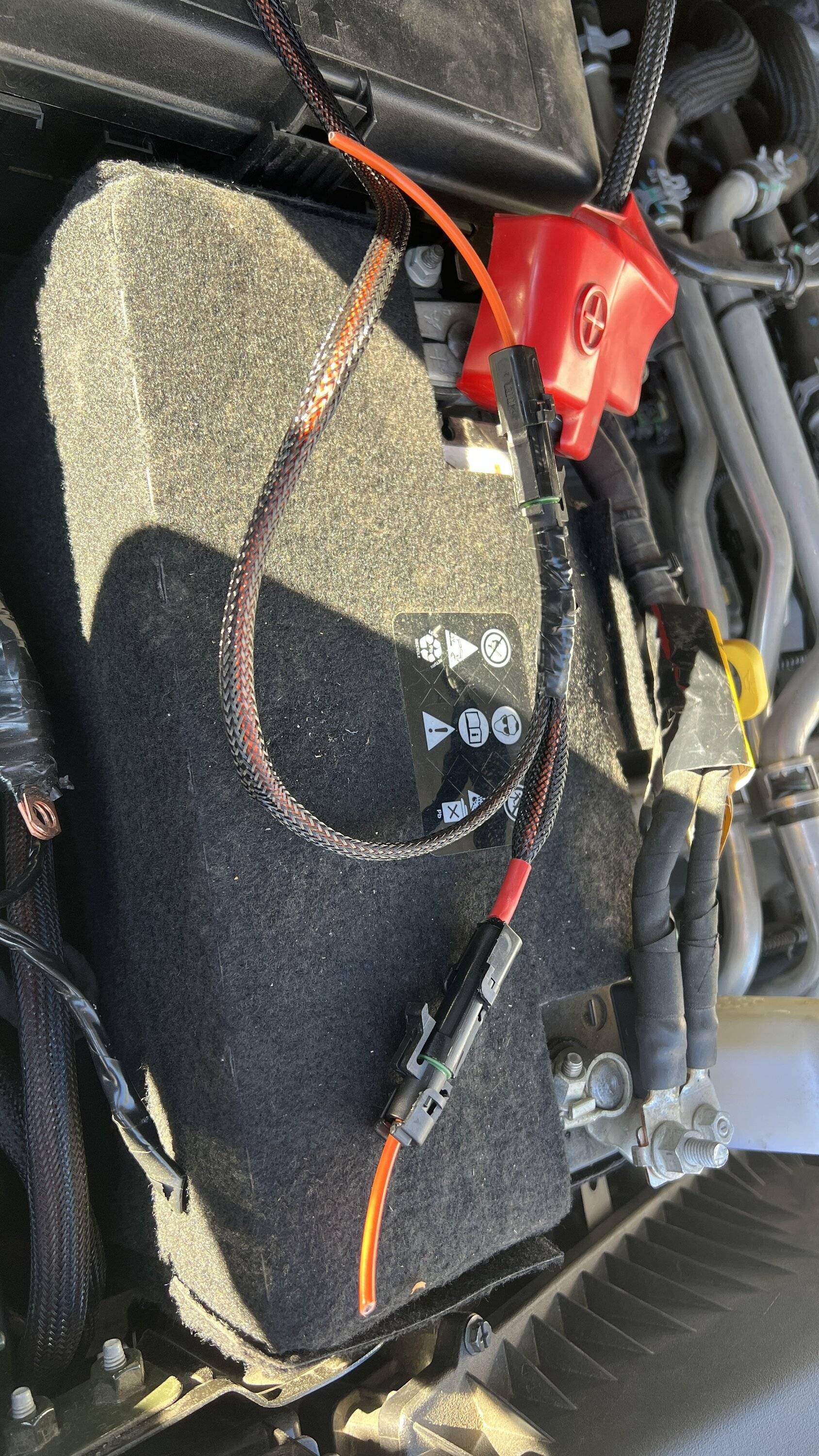
When its single digits out its kinda hard getting much done. But I made another harness that taps into the in cab 12v ignition wire next to the auxiliary switch outputs. Originally I had it strictly going to the switch pros to let it know when to power up. But I also needed to send a ignition signal to the future dual battery system and figured I would make a third tap just in case of another need. I prefer this method over justing those fuse panel tap things. They just dont seem as clean to me. And since this is strictly to provide a signal when the engine is running, the 10 amp factory fuse for that circuit should be more than sufficient since it isnt actually powering anything.
Jeep Gladiator Destination Unknown - 2022 JTR journal image


Jeep Gladiator Destination Unknown - 2022 JTR journal 8ABEAD51-E330-45C0-9BE6-0AD9A7ED9234


Jeep Gladiator Destination Unknown - 2022 JTR journal 9887C87F-6271-4C67-A31C-AAA6A453B2BA
Sponsored

 
OP
OP
chorky

chorky

Well-Known Member
First Name
Chad
Joined
Feb 26, 2022
Threads
175
Messages
3,466
Reaction score
3,801
Location
Montana
Website
www.youtube.com
Vehicle(s)
'22JTR, '06 LJ, '06 TJ GE
Build Thread
Link
Occupation
GIS Specialist
One thing that has been on my mind that I decided to measure today is the fridge slide. Due to the height difference from the bed form, there is about a half inch gap that needs to be filled in. so off to the hardware store we go in search of a solution

Jeep Gladiator Destination Unknown - 2022 JTR journal B75A8054-55F6-46D5-9248-909DD56F3CA0
 
OP
OP
chorky

chorky

Well-Known Member
First Name
Chad
Joined
Feb 26, 2022
Threads
175
Messages
3,466
Reaction score
3,801
Location
Montana
Website
www.youtube.com
Vehicle(s)
'22JTR, '06 LJ, '06 TJ GE
Build Thread
Link
Occupation
GIS Specialist
Today I finished installing the D&C Lucid cowl lights. I must say they are awesome. The signal color matches the factory signal color perfectly and the lights, at least in my neighbors garage, are super bright. I am really curious to put them to work and see how well they do - I also am curious to see how long they actually last. Build quality seems good, but I still do question these circuit board ran LED's. It was very surprising to me to find out the entire cowl, even the center piece, is all plastic. I'm really shocked about that.

So for the install, I hooked the lights up to my pre-installed wiring harness I built. Mentioned earlier, or on another thread, I previously used a harness sourced from Oracle, and thanks to ShadowsPapa, to tap into the 'signal' wire for the parking lamps and the turn signals. The parking lamp tap was used to signal to the switch pros system when the lights were on in order to dim the output of their panel so it's not blinding at night in the cab. The turn signal on either side was ran to the cowl area and terminated into a male end connector. The lights have the female end. Note - plastic is brittle in 20 degrees... I might look for other connector companies in the future. I used the power and ground for the actual light to be connected into a different harness I made running to the switch pro's system. The purpose of this is, in the event the D&C system fails, or breaks or whatever, and replacements cannot be obtained, I will put the factory cowl pieces back on and run standard ditch lights. So by having the light portion with power and ground, and the turn signal with it's own wire, it would not require rewiring the whole system in the future if I chose to revert back - or in the event I sell it and want to transfer parts to a new Gladiator. I am pretty pleased with this install so far - although the cowl will have to be removed again soon to run CB and GMRS wires.

Jeep Gladiator Destination Unknown - 2022 JTR journal IMG_9857.JPG

Jeep Gladiator Destination Unknown - 2022 JTR journal IMG_9863


Also, for anyone else doing this in the future, the factory torx bits work for the cowl bolts. Although I have no clue what to use to remove the hinge bolt.
Jeep Gladiator Destination Unknown - 2022 JTR journal IMG_9864.JPG


Jeep Gladiator Destination Unknown - 2022 JTR journal IMG_9866.JPG
 
OP
OP
chorky

chorky

Well-Known Member
First Name
Chad
Joined
Feb 26, 2022
Threads
175
Messages
3,466
Reaction score
3,801
Location
Montana
Website
www.youtube.com
Vehicle(s)
'22JTR, '06 LJ, '06 TJ GE
Build Thread
Link
Occupation
GIS Specialist
Jeep Gladiator Destination Unknown - 2022 JTR journal IMG_9865.JPG

Jeep Gladiator Destination Unknown - 2022 JTR journal IMG_9868.JPG


jeepfreakedc

Well-Known Member
First Name
Josh
Joined
Aug 13, 2020
Threads
12
Messages
156
Reaction score
54
Location
Atlanta
Vehicle(s)
JT Mojave
Build Thread
Link
By this point in time I have had the JTR on a few day trips. Mostly to run errands and see doctors - so no serious trips or even camping trips yet. But we are getting close!! Well....sorta.

20220804-IMG_8686.jpg

20220730-IMG_8646.jpg

20220619-IMG_8451.jpg


Without going into details, I had to make an urgent trip to Seattle for a second brain surgery. Yep.....#2. It became much more involved than I or the doctors assumed and hoped. But I for as much as I dislike the big city, I have to give Seattle props for having some of the best surgeons and best medical care in the world. After 2 weeks in the hospital, removal of infected skull bone marrow, and 9 weeks of at home central line infusions I was ready to go to my home. But, while staying in the area with my parents for the heavy meds we did take a few day trips, that the surgeons probably would have been unhappy with.

20220919-IMG_9056 2.jpg

20220920-IMG_9067 2.jpg


This was a great time to do some very mild 4x4 trips and see where the JTR sat stock with a heavy canopy (and no other gear). It worked well, but was slightly disappointing with the lack of clearance just due to the 137" wheelbase. I did scrape the factory skid's a few times, and these areas were not at all technical.

20220926-IMG_9133 2.jpg

20220920-IMG_9066 2.jpg

IMG_9046 2.JPG

20220926-IMG_9138 2.jpg
Epic shots brother! ??
 

Sponsored

OP
OP
chorky

chorky

Well-Known Member
First Name
Chad
Joined
Feb 26, 2022
Threads
175
Messages
3,466
Reaction score
3,801
Location
Montana
Website
www.youtube.com
Vehicle(s)
'22JTR, '06 LJ, '06 TJ GE
Build Thread
Link
Occupation
GIS Specialist
Epic shots brother! ??
Thank you! Hoping to get a bunch more in this summer and share them with everyone here. If anyone ever heads this way feel free to reach out, there's so many amazing places to explore!
 
OP
OP
chorky

chorky

Well-Known Member
First Name
Chad
Joined
Feb 26, 2022
Threads
175
Messages
3,466
Reaction score
3,801
Location
Montana
Website
www.youtube.com
Vehicle(s)
'22JTR, '06 LJ, '06 TJ GE
Build Thread
Link
Occupation
GIS Specialist
Today I installed the GMRS antenna and finished routing the GMRS coax to its destination of behind the drivers seat. It was much easier than anticipated - which is nice! Although I did make one, not so bad, but very annoying mistake - see if you can find it.

Figuring out how to mount the antennas was a long struggle. I debated between figuring out a roof mount option, or a more 'typical' option. Whatever the location my hope was to have optimum conditions knowing that Jeep mounting options are not the best. Terrain in my area is very hilly, so reducing as many compromises and complications to signal quality as possible while having an acceptable mount was difficult to sort out. I am still not sold 100% on the chosen option - it will need some field testing to know how well it will truly work. I stumbled across and settled on some EVO cowl mounts. https://evomfg.com/products/jeep-jl-gladiator-a-pillar-cowl-light-mounts-pair-black I liked this option best as it did tie into the windshield hinge mount providing vertical and lateral stability. Costlier than other similar options, but the metal seemed thicker as well - and my CB antenna is quite large and heavy considering other options. A full cowl style mount like the MOPAR option wouldn't have worked due to the cowl integrated lights by D&C designs. Hopefully they allow for a good signal and aren't too far above the metal below.


Before routing the coax, I had to drill out (and paint) the 3/8 hole to just over 7/8 for the plastic insulator to fit. Luckily, the bracket metal was just a hair thinner than the plastic insulator so a good connection between antenna and NMO mount can be made. I also, by recommendation, checked resistance from antenna to end of coax to ensure a good connection. It did read with a little resistance but I'm confident that is because the antenna is painted and I only found a small spot at the tip without paint so it was hard to get the multimeter leads solid on metal.

Jeep Gladiator Destination Unknown - 2022 JTR journal IMG_9869


Jeep Gladiator Destination Unknown - 2022 JTR journal IMG_9870


Jeep Gladiator Destination Unknown - 2022 JTR journal IMG_9872 2


Thanks to a few members here I was able to remove the windshield hinge cover bolt without issue - although it did cause some paint damage which was easy to touch up - Didn't get a picture of that unfortunately but the bolt, or cap, goes into the hinge probably 3/4 of an inch. Tightening it back up to hold the EVO mount in place, however; felt a bit sketch..... It was not on very tight to begin with, and I tightened it a little more than it was originally. The threads are fine and shallow so it is not capable of handling high torque at all. Hopefully it holds the CB/GMRS antennas good enough without stripping out.

Jeep Gladiator Destination Unknown - 2022 JTR journal IMG_9873


Jeep Gladiator Destination Unknown - 2022 JTR journal IMG_9876.JPG


Jeep Gladiator Destination Unknown - 2022 JTR journal IMG_9880.JPG


Jeep Gladiator Destination Unknown - 2022 JTR journal IMG_9881


Jeep Gladiator Destination Unknown - 2022 JTR journal IMG_9883


Several months ago when scouting out wiring pathways, I noticed there was a gap in the body where the windshield meets the lower body panel or cowl. So carefully pulling out the two small panel clips I found the perfect amount of room in the form of the sheetmetal to guide the coax without any pressure of compression from the door being shut. I have not seen anyone else use this path before but I think it is the optimum option especially as coax can be damaged and may need to be replaced over time as compared to wires for switches or other times that can go through unused grommets in the firewall. I will use the same path on the passenger side for the CB coax - which is a little larger in diameter.

Jeep Gladiator Destination Unknown - 2022 JTR journal IMG_9877


Jeep Gladiator Destination Unknown - 2022 JTR journal IMG_9878


Jeep Gladiator Destination Unknown - 2022 JTR journal IMG_9879


Coax was then passed over to the center console, and under the console lip where the carpet is tucked under the plastic. It terminates right behind the seat where the power wires currently are lying. Now I just need to finish making a bracket to mount the radio itself, figure out how/where to route the network cable for the handset, and tie up loose wires.

One item to figure out though is where and how to tie up excess coax. This coax, from Midland, still has 7 feet or so of excess cable, and I don't know currently the best way to deal with that situation.

The antenna does lean slightly forward, but I dont think that really will be an issue. Other than for my OCD... Overall, I am pleased with this project.

Jeep Gladiator Destination Unknown - 2022 JTR journal IMG_9884.JPG
 
OP
OP
chorky

chorky

Well-Known Member
First Name
Chad
Joined
Feb 26, 2022
Threads
175
Messages
3,466
Reaction score
3,801
Location
Montana
Website
www.youtube.com
Vehicle(s)
'22JTR, '06 LJ, '06 TJ GE
Build Thread
Link
Occupation
GIS Specialist
Today I completed two main projects that has me one day closer to getting my rig out of my neighbors garage. I re-ran some new wires to the bed. If anyone remembers, previously I ran 4 8ga wires to the bed for the air compressor. At the time, I though it would be easy to just add more wire later for bed items, but as things progressed and plans somewhat changed, I decided it would be better to only have 2 larger wires, one signal for the compressor, and 2 more later for the rear winch.

I also picked up some red colored wire loom for positive cables just in the event that someone happens to be in that area, they will obviously see a big red cable or two.

To make sure I'm appropriately sizing wire I always refer to a nice chart from Blue Sea Systems. I prefer their chart as it seems to be slightly overbuilt - but considering they primarily work in marine environments where problems are real problems, I would prefer to follow those numbers over others. From their chart, I figured on needing up to 100a continuous to be safe for what will be wired in the bed. So this time I ran 2 4ga wires. One power, one ground. Now, yes I could have grounded to the chassis in the back, but I wanted to offer options for future expansion. I also ran one additional wire powered from Aux switch #2 which powers the ARB compressor relay.

Now my determined 100 amps was not just a random guessed number. If anyone recalls discussion on battery amp hours they will recall I had a spreadsheet to calculate average amperage used based on specs from various manufacturers. ARB calls for a spec of no more than 55 amps of draw for their dual compressor. I will be using a 60a fuse as a test so we will see about that. I have calculated that, at any given time, the max current draw over a sustained time of up to 15 minutes would be 80 amps. So, this provides me with a 20% safety factor. I am comfortable with that. Not to mention the system will have redundant fuses for purposes to be revealed later as the build continues. But for now, 3 wires are going to the bed, and to hopefully be wired up later this weekend.

Wires were ran down the passenger side above the frame zip-tying to the factory harness along the way. It's not perfect like I would have hoped, but there is a bit of a time crunch to get out of the garage.

Jeep Gladiator Destination Unknown - 2022 JTR journal IMG_9895.JPG

Jeep Gladiator Destination Unknown - 2022 JTR journal IMG_9894.JPG


Additionally, I finally pulled the trigger on drilling holes....
 
OP
OP
chorky

chorky

Well-Known Member
First Name
Chad
Joined
Feb 26, 2022
Threads
175
Messages
3,466
Reaction score
3,801
Location
Montana
Website
www.youtube.com
Vehicle(s)
'22JTR, '06 LJ, '06 TJ GE
Build Thread
Link
Occupation
GIS Specialist
For some time now I have been pondering how I wanted to mount plug-in options for a 115v on board battery charger, and wires for future solar or just a non-on board battery charger. I ended up ordering a NOCO through wall 115v plug port, and a CTEK charger, along with another port using a SAE connection (if thats the right name). There were a few requirements for their location. It had to be on the drivers side - my luck I would drive away with it plugged in, and having a plug on the drivers side would be noticed getting in. It also had to be on the canopy somewhere. The canopy is 'replaceable'. The body of the jeep....not as easily. And, they had to be accessible from the outside. I did not want to have to leave a door on the canopy open in order to have something plugged in. Thievery is one reason for this, but also for animals. Plenty of critters roam around at night where I live, and my luck some little cub would be sleeping in the bed of the truck all night, or worse.... The side of the canopy did not offer enough room, so I mounted them between the cab and canopy. Looking back this is actually a really good location as it offers better protection from the sun and elements which should increase the lifespan. However, it remains a question of if I will even be able to get anything plugged in there. I think so.

Jeep Gladiator Destination Unknown - 2022 JTR journal IMG_9888.JPG

Jeep Gladiator Destination Unknown - 2022 JTR journal IMG_9892.JPG


These wires will go to the same 4ga wires that were ran to power bed mounted items. That will then be a direct run back to the engine compartment. For the install of course I used stainless hardware, but also used just a thin beed of black RTV adhesive silicone, to keep all the water out. I purposefully left the shavings on the canopy as I want to see if there will be any oxidization tomorrow. This canopy is 'supposed' to be stainless steel, but I must say it is VERY easy to drill through. Seeing how easy it is to drill through makes me question the supposed 700 pound dynamic load they claim.

Certainly looking forward to getting these wired into the rest of the system. Unfortunately I am still waiting on one component before I can mount the wiring panel.

Jeep Gladiator Destination Unknown - 2022 JTR journal IMG_9893.JPG
 
OP
OP
chorky

chorky

Well-Known Member
First Name
Chad
Joined
Feb 26, 2022
Threads
175
Messages
3,466
Reaction score
3,801
Location
Montana
Website
www.youtube.com
Vehicle(s)
'22JTR, '06 LJ, '06 TJ GE
Build Thread
Link
Occupation
GIS Specialist
Well yesterday was a fun, monumental, and frustrating day in one.

It was the day of installing the Genesis dual battery kit - but...with problems.

So before anyone says how much I dont need it - the primary reason for me doing this kit was not actually to have a aux battery for camping. That is just a side benefit that works for me being in such a cold environment where an always on board lithium would not last. But the primary reason for me to install this system is to get rid of the factory aux battery, and have nice lugs to attach accessories to. After seeing how many people are having troubles with their aux batteries, and the difficulty it is to replace them - I wanted something significantly easier to replace if needed. The Genesis provides that for me.

And it's a good thing because testing the factory battery and aux battery after removal revealed the larger system battery was sitting at 12.5v and the aux was already at 12.3v. Granted I dont drive a ton to commute, and it has been sitting a lot lately, in the cold, but at less than a year old this is what I was worried about with the factory system.

Removing the factory batteries and tray was relatively uneventful. Although I took careful note to keep in mind where everything is and went as I did not want to have issues reinstalling - well... I did anyway. Being careful, using hand tools, and chit-chatting with a friend who is letting me use his garage, the removal took nearly 4 hours. I can't imagine having to do this every single time to replace the factory aux battery - thats insanity.

Oh and I also saw this - looks like the factory way overtightened the hold down bracket. I have not touched the battery components since purchase.
Jeep Gladiator Destination Unknown - 2022 JTR journal IMG_9896


You can see that post 4 and 8 are unused in mine. I would assume #4 has something to do with the rear bed inverter and I dont have one, just the in cab version. I labeled all the posts just to make it easier
Jeep Gladiator Destination Unknown - 2022 JTR journal IMG_9897.JPG


Being sure to protect the positive wires as much as possible - I wasn't sure if any of the others were also hot but based on other videos I have seen they seem to not be.
Jeep Gladiator Destination Unknown - 2022 JTR journal IMG_9898.JPG


There was another change sometime half way through 2021. The Genesis video shows there to be 2 bolts and 1 Phillips screw under the distribution panel to remove the box. Mine had a little 7mm bolt instead.
Jeep Gladiator Destination Unknown - 2022 JTR journal IMG_9899


That tray was unnecessarily difficult to remove. It still boggles my mind this was actually considered a valid design. I know there is the method of going through the fender, but still, batteries are known replacement items - terrible design.
Jeep Gladiator Destination Unknown - 2022 JTR journal IMG_9902.JPG

Jeep Gladiator Destination Unknown - 2022 JTR journal IMG_9903.JPG


Now is when things take a turn and get interesting. The new tray went in relatively 'ok'. Although it still didn't fit perfectly. There must have been even more changes between 21 and 22. There was a bit of a gap at the front of the tray where it uses the two bolts to secure it next to the air box. I was very surprised to learn that Genesis only designed it to use 4 mounting points. So I have a bunch of leftover bolts. I wish they would have designed it to be more secure. I'm sure it is fine, but it could be better IMO.
Jeep Gladiator Destination Unknown - 2022 JTR journal IMG_9904.JPG


This is where my first mistake was made. I got mixed up thinking the factory aux positive needed to remain left off. DONT DO THIS
Jeep Gladiator Destination Unknown - 2022 JTR journal IMG_9901.JPG


Continuing my mistake of storing away the positive cable
Jeep Gladiator Destination Unknown - 2022 JTR journal IMG_9905.JPG

Jeep Gladiator Destination Unknown - 2022 JTR journal IMG_9906.JPG


This was another mistake - after having read about others experiencing issues on various forums due to a change in wiring harnesses sometime between 21 and 22, I mistakenly thought the factory aux negative needed to be attached to the main negative. This caused about 35 minutes of frustration as the negative really did NOT want to go there. I pulled hard - hopefully no strands are broken internally. Eventually it did go, but clearly it was not happy. At this point I knew something just wasn't right. Did Genesis really miss this and not catch that there was a substantial change? Nope...it was all me and my lack of paying attention in excitement of having this system in.
Jeep Gladiator Destination Unknown - 2022 JTR journal IMG_9907.JPG

Jeep Gladiator Destination Unknown - 2022 JTR journal IMG_9910


After putting the distribution box back in is when trouble began. Now - take note that I misunderstood some things a few times. After covering up the factory aux power cable and getting the new batteries in I realized I was supposed to have kept that and tied it to the main power terminal. So that was fun - these batteries are about 50 pounds each. Then, I realized immediately that there would be difficulty in getting the factory aux negative cable to attach to the main negative cable (which goes on the negative post of the new aux battery). This was an issue because I had read a few places (probably incorrectly) that there was a change in 2021 where the aux negative cable goes to body ground, and back to the IBS instead of the original only going to body ground. So, being under the impression that the factory aux negative needed to go to the main negative, I had great difficulty in pulling out enough wire. Now keep in mind this happened only after I already tripped a code of some sort. Eventually though I got it to work, enough wire was pulled - hopefully without damaging any strands, and the aux negative was placed on the IBS. But....a code was still showing. So I decided to go for a drive, and cycle the engine about 7 or 8 times in case it just needed to clear, but it was still there. After returning home, and doing more reading/watching, I realized there was a major mistake and mixup in information. The factory aux negative in fact does not need to be connected to the top of the IBS, but the factory aux positive wire does need to go to the main positive. So I removed the negative, taped it, and temporarily tied it off to the side, while securing the positive correctly. Time for another test drive.
Jeep Gladiator Destination Unknown - 2022 JTR journal IMG_9911


I also took the time to disconnect the positive cable from the battery for a few minutes in order to clear the system in hopes that the 'service start/stop' warning would correct itself. And it did. So after another 15-20 mile test drive, the system was functioning well. I even left the ESS on to see if it would work, and sure enough it did - just the same as other methods folks use to get rid of the factory aux battery but keep the factory main battery - such as removing fuse 42 or disconnecting the aux negative. Unfortunately disconnecting the battery this time also caused the radio to freak out and reset, booting back up as if it was just a sport and not rubicon.... It took some more community forum help, and time (until 2am to be specific) for the radio to re-center itself and once again provide all the rubicon features.

So the Genesis system at the moment is functioning. I do need to go back and clean up some wires and find a nice place to tuck the aux negative cable. Hopefully today I can finish getting the G screen installed and possibly wire up the battery charger/tender.

Jeep Gladiator Destination Unknown - 2022 JTR journal IMG_9912.JPG


I must also give thanks to the folks on this forum who helped to resolve the issues by providing great info! Looking back - I could have done it a different way, and kept the factory group 31 size, and put an additional battery or two in the bed. That could arguably be a better way, and cheaper. But this is a sweet system with all the components included, and without a shop my fabrication options are limited and difficult to accomplish. I also like the G-screen option quite a lot, and having the lugs to attach my primary accessory distribution blocks to is cleaner than a bunch of wires on one single lug. Of course keeping all items taken off for every upgrade in the event I want to revert it back to stock form. Given I had a shop, all my tools, and better fabrication options than the current - I would have opted to keep the factory battery, deleted the aux, and fabricated my own system to go in the bed

After some work this morning I will check to see what battery voltages are for curiosity since it is cold, finish cleaning up some wiring, and begin G-screen install and hopefully battery tender as well.
 

Sponsored

OP
OP
chorky

chorky

Well-Known Member
First Name
Chad
Joined
Feb 26, 2022
Threads
175
Messages
3,466
Reaction score
3,801
Location
Montana
Website
www.youtube.com
Vehicle(s)
'22JTR, '06 LJ, '06 TJ GE
Build Thread
Link
Occupation
GIS Specialist
With my very poor drawing skills and without a wiring diagram designer software I will do my best to explain the system functionality.

System function:
This system works by manually or automatically combining and separating the Two batteries. Both ground cables are connected to the aux battery above the IBS. - everything is above the IBS. The combiner either combines or separates the positives of the batteries. In automatic mode, the system keeps the batteries combined as one so long as the main battery reads above 12.7 volts. As soon as the main battery drops below 12.7 volts, the combiner separates the batteries. The computer constantly monitors the primary battery voltage but draws very little power compared to say the radio. Now this can be overridden manually by either the G-Screen or the under hood switch. There is another optional function I opted for That I need to test and see its true function. The smart alternator will slowly lower charging voltage of the batteries when it senses the main battery is charged. Because the factory standard aux battery is always connected to the main battery when the engine is on and NOT during a ESS event, there is no concern about the batteries not both receiving a charge. However, as the alternator lowers voltage, it can cause a situation where the combiner does not sense a minimum 12.7 volts. In this instance the combiner will the disconnect the batteries from each other even though the engine is on and the new auxiliary battery will not receive a charge. So this engine on feature tricks the alternator into charging at a higher voltage. How it actually does thinI really do not know. But I tied it into the 10 amp engine on battery 12v supply wire that is under the glovebox. Mostly because that wire is also already feeding a engine on signal to the switch pros module so that it will function as well. But I will say there is value in this theory because last summer, I did see a few times where the insturment cluster gague showed charging voltage down the interstate was only at 12.3 or maybe 12.5 volts. So if that is accurate the combiner would disconnect the batteries from each other, which defeats the whole purpose of giving the aux battery a charge while driving. This monitoring of voltage also occurs when the vehicle is locked and off. Meaning if a solar charger or battery tender is connected to either the main or auxiliary battery, when receiving more than 12.7 volts from solar or a charger, it will combine and provide a charge to both batteries.

Take note of two important aspects
  1. The factory auxiliary battery positive cable, when removed from the factory auxiliary battery, is bolted to the factory main battery cable.
  2. the factory auxiliary battery negative cable, when removed from the factory auxiliary battery, is taped up to prevent contact and stowed away disconnected from anything. The cable, due to splices and connections to the negative of the main battery, is still necessary to remain in the vehicle.

When wiring
  1. The main positive cable is connected to the new main positive battery terminal
  2. The main positive cable has an additional wire going to the battery combiner input
  3. the output of the battery combiner goes to the positive terminal of the auxiliary battery
  4. the main negative (IBS) is connected to the aux battery negative terminal
  5. the main negative (above the IBS) also has another wire going to the main battery negative terminal.
  6. The auxiliary battery terminals also have wires going to big lugs to attach accessories. These accessories are essentially powered by the auxiliary battery at all times. When disconnected by the battery combiner, all items hooked to these lugs are powered from the auxiliary battery
  7. when combined, all items are powered by the main battery or alternator as the system is essentially a parallel circuit.

Ok so a few more things. The system has a switch on it under the hood that is an on/auto/off mode. Meaning you can manually force the combiner to combine, or to run automatically, or to be forced to separate the batteries.

Another attachment, called the G-Screen, goes into the cab. It gives functions such as letting you combine, auto, or separate the batteries without using the manual override under the hood. It also provides battery voltages of each battery.

Here is a hand drawn digram since I dont have software for a digital version
Jeep Gladiator Destination Unknown - 2022 JTR journal 244CC74E-54CA-4EA0-B1DB-363C2209E3AD
 

redline61

Well-Known Member
Joined
Jul 23, 2022
Threads
3
Messages
95
Reaction score
156
Location
Idaho
Vehicle(s)
2020 Gladiator
Thanks for the work on the detailed write-ups. Really helps so many people.
 

Jaxmax

Well-Known Member
First Name
Jack
Joined
Jun 28, 2020
Threads
54
Messages
2,856
Reaction score
4,637
Location
Bally, Pa.
Vehicle(s)
Jeeps....... 2021 Mojave , 2019 Wrangler
Occupation
Electrical Manager
Thanks for the dual battery install got me thinking getting the DIY kit and a Redarc DC/DC perhaps.
........Jack
 
OP
OP
chorky

chorky

Well-Known Member
First Name
Chad
Joined
Feb 26, 2022
Threads
175
Messages
3,466
Reaction score
3,801
Location
Montana
Website
www.youtube.com
Vehicle(s)
'22JTR, '06 LJ, '06 TJ GE
Build Thread
Link
Occupation
GIS Specialist
Thanks for the dual battery install got me thinking getting the DIY kit and a Redarc DC/DC perhaps.
........Jack
It really depends on what you want. I strongly suggest starting with doing the math to see what your estimated amperage consumption truly will be. Not for the 1% chance of going to MOAB for a month but your realistic average use. That will help determine what battery system type is best for your application.

If you are going the DC/DC route then the DIY kit really is not helpful - unless you still just want 2 AGM batteries. There are ways to eliminate the factory tiny ESS battery relatively easily and keep the group 31 and factory tr If I was going to go back and do DC/DC then I wouldnt have gotten any of these components. DC/DC can be used with AGM but is primarily used for a lithium setup.

go read post #15 of this thread to see what I mean. I will try and update this thread with the same info now that the Genesis is installed.

https://www.jeepgladiatorforum.com/forum/threads/genesis-batteries-lets-do-some-math.62165/
 
OP
OP
chorky

chorky

Well-Known Member
First Name
Chad
Joined
Feb 26, 2022
Threads
175
Messages
3,466
Reaction score
3,801
Location
Montana
Website
www.youtube.com
Vehicle(s)
'22JTR, '06 LJ, '06 TJ GE
Build Thread
Link
Occupation
GIS Specialist
Today the G-Screen went on. As with most things it took twice as long as planned even though I planned for twice as long as expected - so I suppose that makes 4 times as long as expected.

Anyway - the most difficult part is the part I did not take pics of as it was getting dark out. Cutting parts of plastic trim.

I chose to install the G-Screen in the same location as the Genesis video. Mostly because it really offers, I think, the best viewable location. And it's out of the way. The dash is cluttered enough and there really isn't a very good location there. So, preparations were made and I scored the portion that needed to be removed - reluctantly. I suppose a patch could be made later if needed. This part took quite some time. Probably an hour to be exact. I used multiple scores with a razor blade over and over again which was time consuming and slow due to taking caution to not cause any deep gashes in visible areas. I could have used a little die grinder, but in past experiences, that often leaves plastic melted and not looking so great.

Jeep Gladiator Destination Unknown - 2022 JTR journal IMG_9917.JPG


I did cut a little too far to the passenger side, making it a tight squeeze for the wiring harness. As you can see, there are also wires there that I didn't realize were so close - thankfully I didn't knick any of them!
Jeep Gladiator Destination Unknown - 2022 JTR journal IMG_9919.JPG

Jeep Gladiator Destination Unknown - 2022 JTR journal IMG_9920


Obviously I did make a couple of oopses....but from a normal sitting position, you have to be OCD like me to really know its there. The most challenging part I failed to get pics of. Finding a place to put the control box. It's not very big. Maybe 1.5" by 2.5" by 0.75". But there is hardly any space up there as it is. I had to, reluctant cringe, cut more.... There just wasn't a long enough ribbon wire to put the control box further off to the side. So it is basically right behind the SOS button. Unfortunately, even with a bunch of plastic back there cut and out of the way, it still bows out. But since it is in the middle, it is not super obvious, and again, unless you have OCD like myself, the average person would likely have NO clue. But, I did have to cut 1 retaining clip, and a bunch of 'structural' plastic. I have some worries that it might rattle and make noise now - for which if it does I will have to open it back up and put some felt tape in place.

The rest of the wiring was fairly simple. I ran the data cable the same way as the GMRS on the drivers side - only on the passenger side. Hopefully there will be enough room for the CB coax as well. This was the easiest method and I couldn't find a firewall grommet when the battery box was taken out. I actually prefer this method as future repairs/replacement is much easier. The drivers side grommet that most use is not available as it already has wires going through it for the switch pro system, the 12v engine on signal from under the glove box, and power/ground wires for future additional in cab dome lights. The cable relatively easily passes under the weather seal.
Jeep Gladiator Destination Unknown - 2022 JTR journal IMG_9923.JPG

Jeep Gladiator Destination Unknown - 2022 JTR journal IMG_9924


The rest of the cable simply routes to the Genesis system and plugs in with a weatherproof twist lock connector. The screen is pretty sweet. It's easy to see battery voltages of each battery, turn the auto connecting combiner on or off, or 'boost' mode which just forces the batteries to be combined no matter the voltages.
Jeep Gladiator Destination Unknown - 2022 JTR journal IMG_9926

Jeep Gladiator Destination Unknown - 2022 JTR journal IMG_9922


I also took advantage of being under the hood to clean up my mistake from Friday and find a decent place to store the factory aux negative battery cable. And, put some lugs on the 4ga wires going to the bed as well as put new lugs and electrical connector on the ARB in preparation of hooking it back up.
Jeep Gladiator Destination Unknown - 2022 JTR journal IMG_9925.JPG

Jeep Gladiator Destination Unknown - 2022 JTR journal IMG_9927
Sponsored


Top