Sponsored

SOS. Need help with lower control arm.

Sw00per

Well-Known Member
First Name
John
Joined
Sep 16, 2023
Threads
62
Messages
600
Reaction score
914
Location
California - S.F. Bay (Fog Town)
Vehicle(s)
2023 Mojave
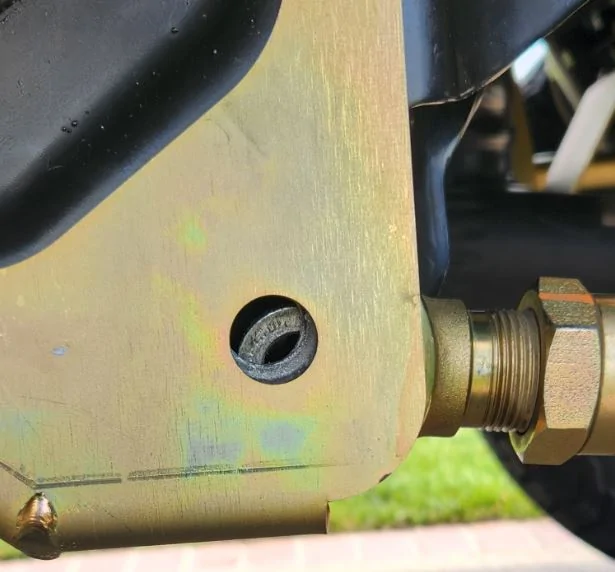
SOS. Need help with lower control arm. As you see in the photo the lower control arm needs to move forward. The bolt came out easy... now to get it back. I did try to jack up the rear a bit but that did not seem to work. Help!
Jeep Gladiator SOS. Need help with lower control arm. LCA
Sponsored


Bandit’s Lair

Well-Known Member
First Name
Jason
Joined
Jul 9, 2025
Threads
29
Messages
2,351
Reaction score
3,855
Location
Southern California
Vehicle(s)
2021 Gladiator Sport S
Occupation
Retired
Do you have the other side in? Is the control arm at exactly the correct length? Can you jack up the axle on 1 side with a jack on wheels and try to shimmy it back a bit? My head is telling me if the arms aren’t set correct and it’s falling short. Something isnt lined up correctly. Go back through and measure everything out again. Better safe than sorry.
 

kevman65

Well-Known Member
Joined
Mar 8, 2020
Threads
51
Messages
3,878
Reaction score
5,751
Location
H
Vehicle(s)
J
Try the floor jack on the side of the axle you're working. Raise and lower the jack to see where it gets you closer.

Ratchet strap on that side of axle back to frame to draw it in.
 
OP
OP
Sw00per

Sw00per

Well-Known Member
First Name
John
Joined
Sep 16, 2023
Threads
62
Messages
600
Reaction score
914
Location
California - S.F. Bay (Fog Town)
Vehicle(s)
2023 Mojave
Do you have the other side in? Is the control arm at exactly the correct length? Can you jack up the axle on 1 side with a jack on wheels and try to shimmy it back a bit? My head is telling me if the arms aren’t set correct and it’s falling short. Something isnt lined up correctly. Go back through and measure everything out again. Better safe than sorry.
Yes the other side is in. I am attempting to install the MC skid plate for the LCA bracket. So the length was set before so that was good. The bolt came out easy but now does not align. I attempted to jack it up from the rear diff and from the axel on the side to move forward without luck. I have also tried a ratchet strap and it helps a bit.

The jeep is on a slight decline toward the rear would that cause it?
 

Sponsored

Bandit’s Lair

Well-Known Member
First Name
Jason
Joined
Jul 9, 2025
Threads
29
Messages
2,351
Reaction score
3,855
Location
Southern California
Vehicle(s)
2021 Gladiator Sport S
Occupation
Retired
Yes the other side is in. I am attempting to install the MC skid plate for the LCA bracket. So the length was set before so that was good. The bolt came out easy but now does not align. I attempted to jack it up from the rear diff and from the axel on the side to move forward without luck. I have also tried a ratchet strap and it helps a bit.

The jeep is on a slight decline toward the rear would that cause it?
Incline or difference side to side could have an effect. If you know the arms are correct throw another ratchet strap or a stronger ratchet strap on it. Axle needs to move to the arm. Maybe a long pry bar and a second set of hands if it’s only a 1/4”.
 

Gizmo

Well-Known Member
First Name
Gary
Joined
Jun 23, 2023
Threads
4
Messages
549
Reaction score
476
Location
West Creek NJ
Vehicle(s)
22 Hydro Blue Sport S MT.
Occupation
Retired Operating Engineer Local 825
Put a jack under the pinion side of the diff and raise it and the control arm WILL move as the pinion rotates up. Their is a flat section i usually just put a bottle jack under it. The springs rotate the pinion down so ya need a jack to rotate it up.once you have tension on the diff with the jack you can take both lower arms off. Use the jack to set your caster and adjust your arms to the mounting holes. I have also just put my foot on the tire and roll it forward or back wards slightly depending on which ya need to go. This is easy to fix no need for ratchet straps. Dont over think it
 
Last edited:

BlueScapegoat

Well-Known Member
First Name
Trevor
Joined
Dec 2, 2018
Threads
14
Messages
1,108
Reaction score
2,681
Location
MN
Vehicle(s)
91 ST185, 04 Ram SRT10, 04 Forester XT, SC'd 05 Rubi, 22 JTRD
Occupation
Air Traffic Controller
Vehicle Showcase
4
Put a jack under the pinion side of the diff and raise it and the control arm WILL move as the pinion rotates up. Their is a flat section i usually just put a bottle jack under it. The springs rotate the pinion down so ya need a jack to rotate it up.once you have tension on the diff with the jack you can take both lower arms off. Use the jack to set your caster and adjust your arms to the mounting holes. I have also just put my foot on the tire and roll it forward slightly. This is easy to fix
This guy has it. Jack the pinion end of the diff, just try not to jack on the pinion flange itself (although it would probably be fine)
 

Gizmo

Well-Known Member
First Name
Gary
Joined
Jun 23, 2023
Threads
4
Messages
549
Reaction score
476
Location
West Creek NJ
Vehicle(s)
22 Hydro Blue Sport S MT.
Occupation
Retired Operating Engineer Local 825
I have simply pushed the tire backwards and with my foot just slid a piece of wood as a tire chock to hold the tire in place until the control arm and mounting hole lined up
 

Sponsored

Jteakus

Well-Known Member
First Name
Teakus
Joined
Feb 19, 2022
Threads
19
Messages
1,802
Reaction score
3,242
Location
Oil City, LA
Vehicle(s)
2020 JLURD, 2022 JTRD, 2017 JKU, 1998 TJ, 1983 CJ-7
Build Thread
Link
Vehicle Showcase
1
Ratchet strap and line up tool were gonna be my suggestions.
 

BlueScapegoat

Well-Known Member
First Name
Trevor
Joined
Dec 2, 2018
Threads
14
Messages
1,108
Reaction score
2,681
Location
MN
Vehicle(s)
91 ST185, 04 Ram SRT10, 04 Forester XT, SC'd 05 Rubi, 22 JTRD
Occupation
Air Traffic Controller
Vehicle Showcase
4
Thanks for all the replies! Success - it took two ratchet straps and an extra set of hands\eyes to align the hole! Now I believe it is the torque is 111 + 65 degrees. Please correct me if I am wrong.
In my experience it's always been whatever torque spec is in the FSM then torque it again halfway down the trail to as tight as you can get it when the factory torque spec was inevitably not enough.

Depending on the type of mount and bushing I've literally just starting to look up the torque specs on the bolts themselves.

Not that I recommend that behavior, of course.
 

Pliny

Well-Known Member
First Name
Philip
Joined
Dec 17, 2022
Threads
21
Messages
228
Reaction score
376
Location
AZ
Vehicle(s)
22 JTR, 99 F250 SD, 24 BMW X3
Occupation
Retired
Now I believe it is the torque is 111 + 65 degrees. Please correct me if I am wrong.
Are those the stock bolts? If they are aftermarket / longer, the "+so many degrees" is only for the thread pitch of the OE bolts. The OE LCA to frame are M16x1.5 Fine. FWIW the instructions for the Mopar 2" lift that I have says torque them to 185 ft lbs.

If the bolts you are using are coarse thread then +65 degrees is going to end up with a higher torque than on a fine thread bolt.
 
Last edited:
OP
OP
Sw00per

Sw00per

Well-Known Member
First Name
John
Joined
Sep 16, 2023
Threads
62
Messages
600
Reaction score
914
Location
California - S.F. Bay (Fog Town)
Vehicle(s)
2023 Mojave
Are those the stock bolts? If they are aftermarket / longer, the "+so many degrees" is only for the thread pitch of the OE bolts. The OE LCA to frame are M16x1.5 Fine. FWIW the instructions for the Mopar 2" lift that I have says torque them to 185 ft lbs.

If the bolts you are using are coarse thread then +65 degrees is going to end up with a higher torque than on a fine thread bolt.
They are after market Metalcloak supplied 5/8 bolts. They appear to be the same thread pitch as the factory bolt.
 

Pliny

Well-Known Member
First Name
Philip
Joined
Dec 17, 2022
Threads
21
Messages
228
Reaction score
376
Location
AZ
Vehicle(s)
22 JTR, 99 F250 SD, 24 BMW X3
Occupation
Retired
They are after market Metalcloak supplied 5/8 bolts. They appear to be the same thread pitch as the factory bolt.
If they appear similar to OE, then they are probably UNF 5/8 - 18 which has 18 threads per inch.

The OE bolts have thread pitch of 1.5 mm, so 25.4 / 1.5 = 16.9333..... threads per inch.

There are reasons that I didn't end up in a mechanical engineering / material science career but 65/360 x 1/18 = ~0.010031 inches of additional compression / bolt stretch. Whereas 65/360 x 1/16.933 = ~0.010663 in. (25.4 / 1.5) / 18 = ~0.94074. So ~6% less.

I suspect the actual clamping force delivered to the assembly is a function of the actual material the bolt is made from, as well as the difference(s) between metric class 10.9 and SAE grade 8.

I learned this lesson when I initially went to install the LCA skids on my JTR. The longer aftermarket bolts that came with the skids were coarse thread, and trying to use the +degrees spec resulted in them being drastically overtightened.
Sponsored

 
Last edited:


Top