Radio Guy
Well-Known Member
That’s a complex question and will vary with different antennas and mounting locations. This will probably go long so lets start with a perfect flat infinite size ground plane made of copper. I’m talking covering your entire city in copper sheet then plant your antenna in the middle. That will pull the radiation pattern down towards the horizon the most with equal signal in all directions around a compass. It will also give the lowest impedance at the feedpoint which is about 35 ohms for a 1/4 wave whip and the most capacitance between the whip and ground plane.Radio Guy, I have a question regarding how much ground plane is best VS how much is fine and wouldn't make much of a difference.
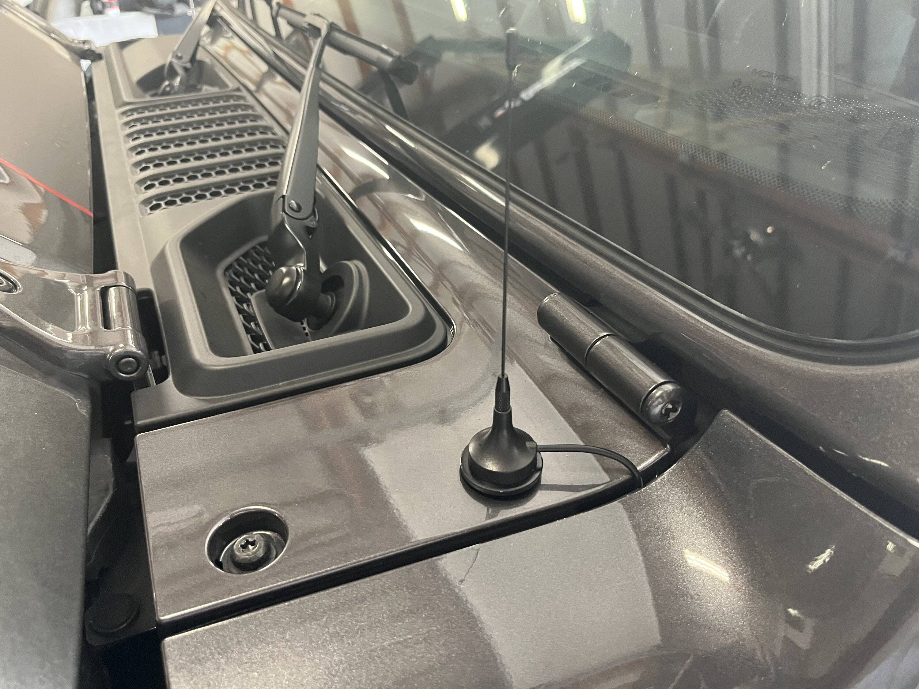
The photo of the antenna above on the red crossbar has plenty of counterpoise (as long as its grounded to the crossbar) for a 1/4 wave gmrs antenna.
There are many 1/4 wave whips where the operator attaches a 1/4 wave counterpoise and it works fine. I think in the mobile environment it can't make much difference.
What do you think?
Thanks and 73, Tim
Now make the ground plane 1/2 wavelength across or 1/4 wavelength out from the antenna in all directions and the radiation pattern will point up above the horizon a bit and with equal signal around a compass. The feedpoint impedance will be slightly higher but still less than 50 ohms with less capacitance between the whip and ground plane.
A solid 1/2 wavelength across solid ground plane with the whip in the middle is the gold standard, 1 for being the smallest size to provide a near perfect ground plane and 2 for providing 1/2 wave round trip for RF on the ground, 1/4 wavelength out from the whip then reflecting off the edge and back to the feedpoint mimicking the feedpoint impedance and cancelling radiation in the ground plane. The latter being more applicable to wire or rod radials vs a solid metal sheet with the solid sheet being more forgiving and the radials having the ability to be individually tuned or de-tuned, which can be good or bad.
Now move the whip to the edge of the gold standard 1/2 wavelength across solid ground plane, which would be similar to a roof mount at the edge of a roof and now half the whip is sitting over an “adequate“ ground plane and the other half is hanging in “free space”. The radiation pattern towards the ground plane will be pulled down towards the horizon, not exactly at it but slightly upwards and the pattern away from the ground plane will point significantly upwards with much less signal at the horizon. As you drive the vehicle around in a circle and transmit there will be a very noticeable change in signal level which can be maybe 6dB or more.
In this example the capacitance between the whip and ground plane is reduced a lot which will raise the feedpoint impedance causing you to lengthen the whip to get back some capacitance but detuning the antenna in the process. Finding the best match will be a compromise and some antennas may
achieve an acceptable match and others may not and things like being a full 1/4 wave whip vs shortened with a loading coil, location along the whip of the loading coil and other factors will determine the potential match.
A CB antenna “wanting” a 1/2 wavelength across solid ground plane of 18ft diameter is much more of a challenge than a UHF GMRS antenna only “wanting” a 12in dia ground plane. A CB antenna in the middle of an extended van roof seems like overkill but it’s actually a fraction of the gold standard 18ft diameter that it wants, but any CB antenna will work great on a metal van roof.
Put the Same CB antenna on the edge of a Gladiator hood (NMO trunk lip mount) and you are starving it for ground plane. The hood is a fraction of the needed ground plane at 27MHz and the radiation pattern will be above the horizon in all directions and especially looking towards the rear and side away from the hood with a significant loss of gain at the horizon. The feedpoint impedance of this hood mounted CB antenna will be well above 50 ohms and you will be compromising the tuning to get an acceptable match, which may not be possible with some antennas. Adding some conductive tape under the plastic cowl pieces to extend the ground plane slightly towards the rear as I did on my Mojave will have little effect at 27MHz CB frequencies due to its wavelength of about 36ft.
Swap the edge of hood mounted CB antenna for a GMRS antenna and now the hood is way bigger than the gold standard of 12” dia needed for UHF. Problem is the mount is at the very edge of the hood and one side of the antenna is nearly floating in air with a plastic cowl behind the hood. The radiation pattern will be great in the direction of the most hood mass and will be lacking in the direction of no ground plane. Since there is a lot of ground plane at UHF in some directions I think any UHF antenna will tune up and provide a good match. In this case adding a half square foot of conductive tape under the plastic cowl piece to extend the ground plane will help with the radiation pattern to the rear of the truck because a full wavelength at UHF is about 24in and even a small mount of metal can make an improvement.
Lets move the antenna mount to a 1” X 6ft long cross bar sitting 2” above the roof. The roof is fiberglass providing no ground plane and even if it were placing the feedpoint away from the ground plane increases impedance and adds ground loses which equate to loss of antenna efficiency. So you have this 1in wide by 6ft long metal rod for a ground plane. At UHF it’s plenty long in two very narrow directions but totally lacking everywhere else. Radiation pattern will be up towards the clouds in most directions and a little lower off to the sides it will come down a little but nowhere near what a hood mounted antenna might do. The antenna is high and in the clear compared to a hood mount but it’s not seeing the horizon where all your buddies radios live.
Replace the UHF GMRS antenna with a CB antenna needing about 17X more ground plane and it’s a disaster. There just isn’t enough ground plane to do anything for the radiation pattern at the horizon and a huge loss of capacitance between the whip and ground plane and it will be nearly impossible to get any CB antenna to match sitting on a 1in X 6ft long metal rod.
If you could extend the metal rod to about 9ft long with the CB antenna mounted at one end you have made a 1/2 wave inverted V dipole which is a real antenna and can perform quite well in two directions broadside to the dipole. But both halves of the dipole, the whip and 9ft cross bar are the hot radiating parts of the antenna and with the cross bar being horizontal this dipole will radiate on a 45deg slant if it were in free space causing about a 3dB degradation to vertical mounted whips around you and less off the non broadside. Plus the crossbar is sitting horizontal above a metal truck which will completely interfere with its radiation pattern and capacitance between whip and counterpoise or ground radial, the other half of the antenna. Bottom line is you will never get any performance out of a CB antenna mounted to a cross bar above a roof.
I‘ll stop here but there is a lot more to antennas, ground planes and grounding in general. Antennas are very complex and I am no expert, although I‘ve worked with them all my career In addition to installing and tuning about 1,000 of them at one of my first jobs. I hope my rant has answered at least one of the questions.
Sponsored